This thread has been locked.

If you have a related question, please click the "Ask a related question" button in the top right corner. The newly created question will be automatically linked to this question.

Sine-wave PWM module frequency issue

Other Parts Discussed in Thread: TMS320F28335

Hi Mr.Frank Bormann,

As you suggested, I've tried to modify the sine-wave example for F20827 for my F28035 controller, and it worked (I think). Thank you.

I have two questions now,

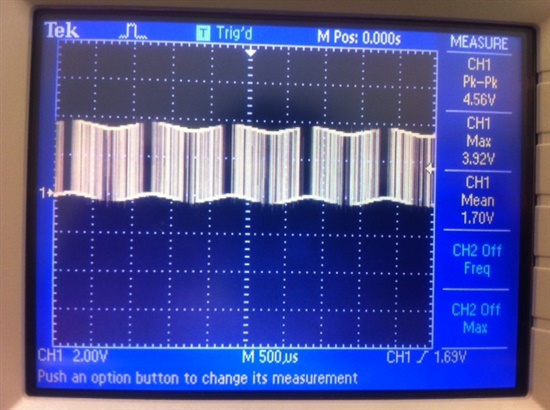
1. Am I supposed to have the result as shown in the document  and as shown below? Because I didn't get one like this.  What I got was a PWM signal with time-varying duty-cycle, and I think that makes sense. So, at any time, the duty cycle within each PWM period is different, and the waveform is changing from moment to moment. But I don't know what the screen-shot below is about ?


2. Second question: It seems like I have to keep TBPRD equals to 60, as it was set up in the example, otherwise I would not get the result I described above.

      a. If I assigned a smaller value to TBPRD, say 50, I wouldn't get anything.

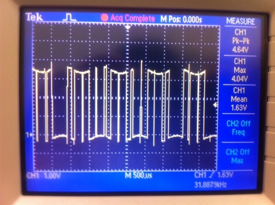
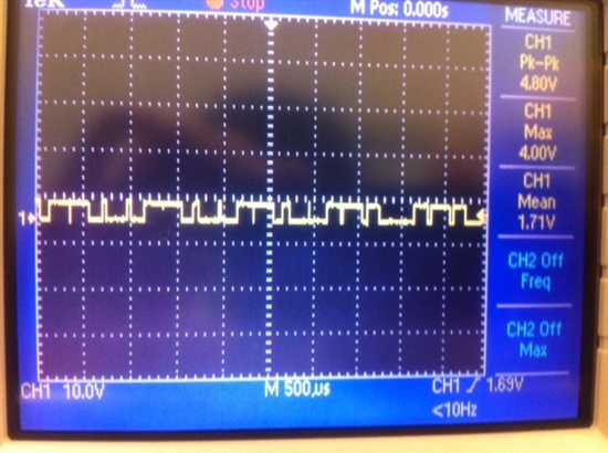
      b. If I assigned a bigger value to TBPRD, say 600, I would get PWM with time-varying duty-cycle, but duty-cycle of every period is changing at the same rate. So, if I press

          'RUN/STOP' button on the oscilloscope, I will always get the same waveform. And I don't think that is correct.

With TBPRD=60, the Sine-wave frequency is 976 Hz, but I need a 60 Hz sine-wave signal.


Thank you


  • It looks like the screen-shot picture is not showing here. It is actually the picture on page 30 of the example document.

  • This is what I got, when TBPRD=60.


    Press 'RUN/STOP',


    If I zoom out, it looks like this


  • Answer1: 

     Yes, the PWM signal uses duty-cycle, which vary over time - exactly by each period of the PWm carrier signal. The duty cycle is proportional to the instantaneus value of the sine, that is all basics. If you scope the PWM signal, you get exactly what your screenshots show. If you read the explanations at the top of page 30, you will find that you need an integrator (low pass filter) to build the resulting sinusoidal signal (2nd. waveform at page 30).

    Answer 2:

    The calculation of the resulting sine frequency is explained at page 31 (top) and 33 (step #10). For the examples I used 512 periods of the PWM carrier signal to buils 1 period of the sine.If I run the PWM at 500kHz, then 500kHz/512 equals 976 Hz. To produce a PWM of 500Khz with a 60MHz device, the TBPRD must be initialized to 1/2*60MHz/500KHz = 60 (see page 33). The duty cycle is then varied between 0 and 60 (or 0 and 100%) - see last line at page 33.

    If you would like to produce another sine frequency, you have to do the math again. If you would use this example fo 50Hz, just change the PWM - frequency to 25,6kHz, calculate a new TBPRD and adjust the duty cycle to stay between 0 (min) and TBPRD (max) according to page 33/34.


  • Hi,

    I have used the method explained by Mr. Bormann to generate a sinewave of 3kHz for the TMS320F28335 DSP (150 MHz clock). I am using the same program of the tutorial.

    The calculate that I have done:

    Fsin = 3000Hz; Tsin = 3.333333333333333e-4s

    The sine wave lookup table in the ROM of the F28x, has 512 samples for 360 degree

    TPWM = 3.333333333333333e-4s/ 512 = 6.510416666667e-7s  ---> freq PWM = 1535999.999 Hz = 1.536 MHz

    TBPRD = 0.5 * TPWM / (TCPU * HSPCLK * CLKDIV) = 0.5 * 6.510416666667e-7s  / ( 6.6667 ns * 1 * 1) = 48.828125   --->TBPRD = 49

    The DSC crash!

    I have tried some proof, and I have seen that change TBPRD = 56 I have a good sinewave of 2.61 kHz.

    Setting TBPRD lower than 150 (that give a good sinewave of 976 Hz) the frequency of the sinewave rise up, but under TBPRD = 56 the DSP crash.

    There is a method to obtain a sinewave of 3kHz?

    Thank you!

  • I have partially resolved using a 256 sine table! Now I can arrive at 3 kHz!

    But remain a problem: the excursion of the signal at output epwm pin is about only 0.4 V rms

    I don't understand why!

  • Resolved also this problem: I have discovered that the probe of the oscilloscope have a filter inside! Now the wave is 0V to 3.3Vt!

  • Hi there,

    Can you please tell me how I can find the tutorial? I really need to find out how to make Sin wave inF28335.

    Thanks