This thread has been locked.

If you have a related question, please click the "Ask a related question" button in the top right corner. The newly created question will be automatically linked to this question.

InstaSPIN-BLDC

Other Parts Discussed in Thread: CONTROLSUITE, INSTASPIN-BLDC, DRV8301, TMS320F28035, DRV8312, DRV8302

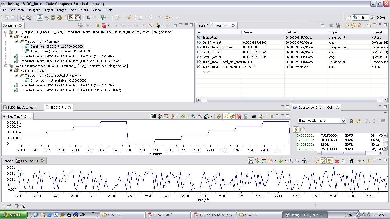
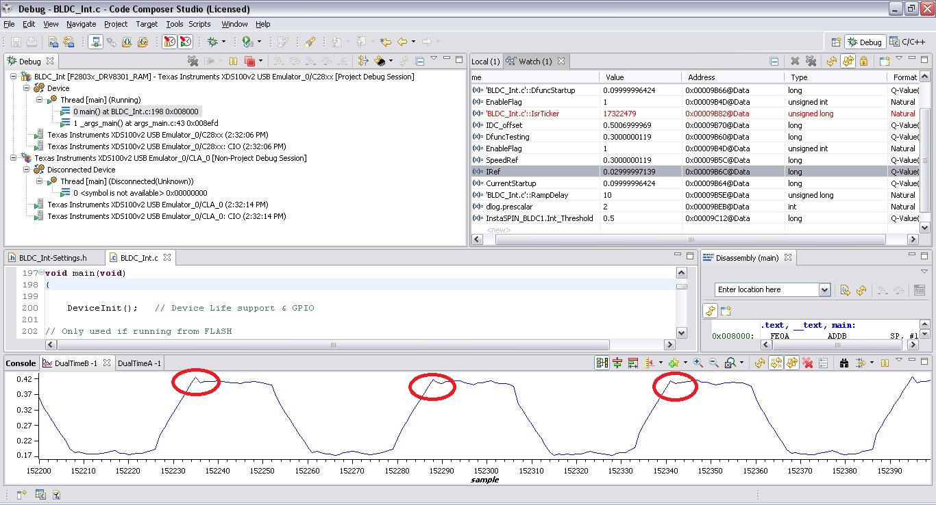
Refer to InstaSPIN_2D00_BLDC-Sensorless-Control.pdf in C:\TI\controlSUITE\development_kits\DRV830x-HC-C2-KIT_v100\BLDC_Int\~Doc ,  it's talking about config,set up and testing of BLDC_Int only. There is no details of InstaSPIN-BLDC module.

So, How to get source code or document explain of "InstaSPIN-BLDC" module ?  Thank you.

  • Sutthinee,

    Sorry, there is a little bit unclear in some of the naming in folders / documentation.  InstaSPIN-BLDC = BLDC_Int (Integration technique). This is being cleaned up in the next controlSUITE push.

    As for the InstaSPIN-BLDC.lib I agree that it needs a library document explaining the concept.  We will be releasing this document probably in December when we release InstaSPIN-BLDC solutions for other kits / MCUs.

    The general idea is explained in the User Guide above, at www.ti.com/instaspin-bldc , and the interface to the library supplies some additional clarity

    C:\ti\controlSUITE\libs\app_libs\motor_control\libs\InstaSPIN-BLDC\v100\include\

    typedef struct

    {

    int32 Vag; // Internal: Vag input -- contains real Va + VaOffset --> referenced to ground (_iq)

    int32 Vbg; // Internal: Vbg input -- contains real Vb + VbOffset --> referenced to ground (_iq)

    int32 Vcg; // Internal: Vcg input -- contains real Vc + VcOffset --> referenced to ground (_iq)

    int32 Van; // Internal: Va to neutral (_iq)

    int32 Vbn; // Internal: Vb to neutral (_iq)

    int32 Vcn; // Internal: Vc to neutral (_iq)

    int32 VaOffset; // VaOffset (_iq)

    int32 VbOffset; // VbOffset (_iq)

    int32 VcOffset; // VcOffset (_iq)

    int32 Int_Threshold; // Input: Integration threshold where a commutate happens (_iq)

    Eintbool Vint_lockout; // Internal: Flyback voltage lockout flag

    int32 *Vphase; // Internal: Pointer to the Phase voltage to count (_iq)

    int32 V_int; // Output: Integrator (_iq)

    Eintbool Comm_Trig; // Output:  Commutation trigger impulse

    Uint16 State; // Input: Values 0 to 5

    } INSTASPIN_BLDC;


    Sorry, source code is not given out for this technique.

  • Dear Chris,

    Thank you for your reply. Will wait for document releasing in Dec. If you can expedite, kindly please help. 

    I have more question related to InstaSPIN_2D00_BLDC-Sensorless-Control.pdf , Page#11 Figure 6 : Graph for Build Level 1.

    We are testing my our design board for Level 1, we found that the waveform of BemfA, BemfB, BemfC of my own design board are different from the Figure 6 on Page#11 and the value of BemfA, BemfB, BemfC also differ from Evaluation board.  See attached files[BEMFx_value.xls, Graph_mod6_BemfA.jpg].

    Differents of my board vs Evaluation board are :=

    1) Package:  I use 64pin TQFP instead of 80pin LQFP (Evaluation board).  Pin compare is attached file[F28035_64PIN_80PIN.xls]

    2) Mosfet : I use brand IR p/n IRFB3607PBF instead of Vishay p/n SUM110N06-3m9H.

    Could you please advise how to find tuning the waveform to be similar to the waveform of Evaluation board in Fugure 6 ?  Which parameter or variable should be adjust to match with my own design board ? Please help to suggest.

    Thank you.

    6545.BEMFx_value.xls1754.F28035_64PIN_80PIN.xls

  • Bemf is derived from the voltage sampling. What are the differences between the voltage levels and sampling circuit between the DRV8x kit and your hardware?

    Did you run this motor with the DRV8x HW and the GUI?  I'd be interested to see what the waveforms look like through the GUI and what Vth level you tuned to.

    I think this is one of the first motor solutions where it's actually easier to do all of the development and tuning from the GUI itself.

    Attached is also a "lab" that will be in controlSUITE on the next update. You might find it useful to understand some of the GUI features and how to tune the motor.


    InstaSPIN-BLDC_Lab.pdf
  • Dear Chris,

    I cannot prepare waveform through the GUI because my own design board don't have serial. 

    But by  checking/debuging my hardware, we found that the waveform of DRV8301 have something wrong. Please refer to attached file.

    The Eval board, input PWM waveform of DRV8301 same as output Gate waveform of DRV8301

    But My board, input PWM waveform of DRV8301 differ from output Gate waveform of DRV8301 and always have Fault waveform.  *** Refer to attache file.

    We built 4 boards, those are the same problem same waveform. So, I think may something wrong on my hardware.

    I also attached schematic here. Could you please help to take a look and suggest what is the possible root cause ?  Thank you.

    3835.BLDC_V1_12Oct10.pdf

     8267.DRV_POWER_BASE.pdf

  • Sutthinee,


    Table 1 on page 16 of the datasheet shows the various fault modes for the device and reporting for each fault.  Since this appears to be an "unlatched" fault, we can cross those off the list.  

    Please step through this table and verify that the voltages are OK and then we can cross those off the list as possible problems.

    If you can also tell me what the register settings are that you programmed through SPI, that would help me determine if there is an over-current event.  For this, I would also need to have a current probe shot of the current when the fault is occurring.


  • Dear Ryan,

    Let you know first, we are testing both Eval & My own design board without connecting Motor.

    By checking OCTW & SPI status register, It's maybe fault mode#2[DVDD undervoltage]. But after check pin DVDD, the voltage is 3.3V which is correct.

    Others pin Voltage are following:

    GVDD =    11.5 V
    CP1    =    0.0 V
    CP2    =    12.0 V
    DVDD =    3.3 V
    AVDD =    6.5 V
    PVDD1=    33 V
    BST_C =    10.5 V
    BST_B =    10.5 V
    BST_A =    10.5 V

    All voltage look OK. So, we don't no why Fault is occured and Gate drive output have no correct waveform. Do you have any others suggestion ??

    I have attached file(CP2_VCC waveform.doc) which is waveform of VCC & CP2 of Eval board and LA board. Both waveform are the same.

    And also attached file(Myboard_Fault_Waveform.jpg) which is Fault waveform since start running code. ***Yellow line is Fault, Pink line is OCTW.
    - Beginning of code, Fault is High. Then DRV8301 is reset, Fault go low then high.
    - After that code delay 50ms then RUN motor control, Fault occur immediately like yellow line in waveform.

    Regarding the SPI, we used the same code except Eval board used SPIA but My board used SPIB. Codes are attached(Code.rar).

    FYI, Eval board used TMS320F28035 package 80pin LQFP but My board used package 64pin TQFP. Pin compare is attached[F28035_64PIN_80PIN.xls]

    0535.CP2_VCC waveform.doc


    1780.Code.rar

     5270.F28035_64PIN_80PIN.xls

  • Sutthinee,


    I am going to need you to look at GVDD, DVDD, and AVDD with a scope to see if they are collapsing.  The decoupling capacitors on those pins are very sensitive to grounding.  The capacitors on those 3 pins need to be as close as possible to the device and the GND side of the capacitor needs to be closely connected to the PowerPAD ground.  Is the PowerPAD of the DRV8301 (exposed metal tab underneath the IC) properly soldered to the board.  This ground pad is the ground for the entire IC and needs to be soldered to the PCB.  The decoupling capacitors for the 3 regulators mentioned above need to be routed closely to this GND point.

    You will actually notice 2 blue wires on the EVM.  These were added as we initially had problems with this same thing on the EVM.  The blue wires bring the GND points from th3 3 decoupling capacitors back to the PowerPAD.


  • Dear Ryan,

    Thank a lot for your suggestion. Now, my board can drive & control motor. 

    But I have one more question, Do we need to re-tuning DRV8301 when we change MOSFET ? 

    Now,

    - Eval board vs Myboard.  There are 2 differents(R-shunt, MOSFET). Refer to attached file(Eval_mosfet.jpg & Myboard_mosfet.jpg). 

    - We are using tuning value which got from Eval to use on my board. We found that compare to Eval board, my board control motor are not much smooth.

    -We think, we need to re-tuning when we change MOSFET & R-shunt.  We trying to tuning parameter relate to MOSFET. But we are not sure we done it all.

    So, Could you please advise what are parameters we need to tuning when we change MOSFET ?  Thank you.


  • Are you using that current sense for a current loop, or just over current protection?

    For tuning the commutation with InstaSPIN-BLDC recall that you are looking at the Bemf value on each phase during the off time.  But you are using a single threshold value for each.  So you should verify

    1. balanced feedback circuits. at steady state are you getting near identical Bemf readings on each leg?

    2. compare this to the DRV83xx board. What are the magnitude of the Bemf. If they are different, why? 

    If you are doing a current loop, you should take a similar thought. What is the quality of the current signal you are sampling. Compare it to DRV83xx kit. If it is different, why?


  • Dear Chris,

    Thank  you for your advise. 

    By our latest testing after changed Mosfet to new IR p/n  IRFB3306PBF, the waveform look nice and we can control motor smoothly same as eval board.

    Now, we have some more questions would like to verify .

    1) What are different between using "Current mode"  which done by MCU(TMS320F28035)  & "Current limit" which done by DRV8301 ? 

    2) By my understanding, 

     "Current mode" will use MCU to detect current at R-shunt to control torque of motor but "Current limit" will use DRV8301 to detect current from RDSon of mosfet for safety & shutdown DRV8301 when some mistake occured.  So, we need to use both "Current mode" & "Current limit" together.

     Is it correct for my understanding ?   Thank you.

  • Correct. 

    Current mode is an inner current/torque loop. You will typically want to run this as a cascaded loop inside of a speed loop. Meaning when the speed loop needs to increase/decrease speed it will send a new torque/current reference. You will tune that inner loop depending on how soft or stiff you want the current to increase.


    Current limit is a protection for the power electronics. In most cases you are looking at a single current shunt and will take action with the MCU PWMs, however with the DRV83x devices they can monitor the current themselves shut off switching before any damage is done.


  • Specifically to the the DRV8301, the current protection/limit operates on measured drain-source voltages across the output FETs.  You can set the Vds threshold via internal register settings based on the Rdson on the output FETs.  

    Given variance in the Rdson of the FETs over temperature and process, the current protection in the DRV8301 is meant purely to protect the FETs from short circuits or other fault conditions that would produce a current in the FETs much higher than your chosen operating point.  It is not meant for precise current control.  


  • Dear Chris,

    Thank you for your reply.

    Base on CLA, HRPWM didn't use in BLDC sensorless.  We are thinking to move from TMS320F28035 to lower feature p/n TMS320F28030 for cost saving. But I have one question would like to verify before make decision,

    There are different on ADC's conversion time

    F28035    4.6MSPS, Conversion Time=216.67ns

    F28030    2.0MSPS, Conversion Time=500.00ns

    If we move to F28030, do we need to change/re-setting software code related to ADC ?  If yes, which parameter ? Please suggest. Thank you.

  • The ADC clock for this project is set to the chip default which is /4

    this is found in 

    C:\ti\controlSUITE\development_kits\DRV830x-HC-C2-KIT_v101\InstaSPIN_BLDC\BLDC_Int-DevInit_F2803x.c

    // LOW SPEED CLOCKS prescale register settings

       SysCtrlRegs.LOSPCP.all = 0x0002; // Sysclk / 4 (15 MHz)

    This means the ADC is running off of a 60 / 4 = 15 MHz clock.

    There are 13 cycles per ADC conversion, so 1/15MHz * 13 = 867ns conversion, which is allowed for F28030

    To get 500ns you would need to use a 26 MHz Low speed clock....which means you need to run the CPU at 52 MHz and divide by two.


    So no, you don't need to change any code. You should just be able to change your target device to F28030, make sure the memory map is correct, and compile.


  • Disregard above, completely wrong.

    On Piccolo devices the ADC clock comes from the main CPU clock.

    You can divide by 2 or 4 (see ADC register settings), but that is not done in the code.

    So to change the code to meet the F28030 ADC timing spec you will need to change every instance of the Acquisition Window to the minimum from datasheet table 6-37

    AdcRegs.ADCSOC0CTL.bit.ACQPS = 6;

    to 

    AdcRegs.ADCSOC0CTL.bit.ACQPS = 23;

    in 

    f2803xileg_vdc_BLDC.h


  • Dear Chris,

    Thank for your advise.   I have some more questions.

    1)  IRef : Changing the running current in per unit.  Is it related to BASE_CURRENT ? 

    For example :
    #define BASE_CURRENT 20.625 , If we need current to drive motor about 12A, we need to set IRef as following.
    _iq IRef=_IQ(0.6);
    Running current = 0.6*20.625 = 12.375 

    Is it correct for my understanding ?

    2) I'm not clear about the Cascade mode. Could you please explain more about case CASCADE below ? Why "pid1_idc.term.Ref " didn't set = IRef  same as Current mode ?

    case CASCADE:
         SpeedRef = Gui.Ref;
    // ------------------------------------------------------------------------------
    //    Connect inputs of the PID_REG3 module and call the PID current controller
    //  macro.
    // ------------------------------------------------------------------------------ 
          if((ClosedCommutationFlag == 0) || (SpeedLoopFlag == FALSE))
    {
          pid1_idc.term.Ref = _IQmpy(Gui.CurrentStartup,mod_dir1.CntDirection);
    }
    else
    {
    // ------------------------------------------------------------------------------
    //    Connect inputs of the PID_REG3 module and call the PID speed controller
    //  macro.
    // ------------------------------------------------------------------------------ 
          pid1_spd.term.Ref = SpeedRef;
          pid1_spd.term.Fbk = speed1.Speed;
          PID_GR_MACRO(pid1_spd)
         
          pid1_idc.term.Ref = pid1_spd.term.Out;
    }
    pid1_idc.term.Fbk = _IQmpy(IDCfdbk,mod_dir1.CntDirection);
    PID_GR_MACRO(pid1_idc)

  • 1) IRef is the start-up current (Id) to command. It should NOT be set to something high like 0.6.  Again, it is JUST the start-up current/torque.  If you search for the IRef term you will see it is only used for start-up. For the DRV830x we set this to 0.04 for default start-up.  For your motor you may need to increase this.  But yes, this value is a per unit representation of the full scale current (BASE_CURRENT)


    2) For the first if statement, this case is if we are in start-up mode (we have not closedcommutation) so we drive the Id (current/torque loop) with the start-up current IRef (multiplied by a direction -1 or +1)

    else we run our outer speed loop and feed the Id (torque/current) loop with the output from the speed loop, and then run the current/torque loop.


    Make sense?


  • Dear Chris,

    Thank for your advise.

    Now,we got new H/W PCB board. *** This should be the final one. 

    We are verifying this board follow the " InstraSPIN-BLDC Sensorless Control.pdf."
    We are still unclear about the current loop in Level 6. We would like to verify with you.

    What is the relation between variable " IRef " and "actual phase current" at BLDC Motor ???

    For example testing, 

    1) DRV Gain = 40, Base Current = 13.75(R shunt =3mA), IRef = 0.1   

    The control current should be = 13.75*0.1 = 1.375A. 
    But Why the "actual phase current" which we see from scope 's current probe = 22.9A ?
      *** waveform is attached

    2) DRV Gain = 40, Base Current = 13.75(R shunt =3mA), IRef = 0.05

    The "actual phase current" we got = 10A-11A

    3)  DRV Gain = 40, Base Current = 13.75(R shunt =3mA), IRef = 0.025

    The "actual phase current" we got = 5A-6A

    From result above, could you please explain more about relation between variable IRef, Base Current, Actual Phase Current ? Thank you. 


  •  

    You say your circuit is set-up to scale 0-13.5A, correct?  If there are 22.9A currents how do you expect to represent that on 0-13.5A?  Why did you try to change the base current to a value lower than currents you expect to sample?

    The DRV830x-HC-C2-KIT has a BASE_CURRENT of 82.5A

    That means after the resistor divider (scaling) to the ADC, the maximum voltage to the gain stage will be 0.33.  This gets a x10 gain to 3.3 which is seen by the ADC as 12-bits (code 4096) ideally.

    If you change the GAIN to 40, it means the input from the resistor divider saturates at 0..0825V, so the current represented is (82.5/0.33 * 0..825) = 20.625V

    The PGAs are in the device so that you magnify very small samples at particular places - for example low load where the current is very small you can gain up the signal and get better resolution. But you need to realize when you are doing this and take note because your ADC 12-bit digital values now don't have the same representation as when you didn't gain up the signal.  Basically at low current levels (when the input to the PGA is < 3.3V/80) you can change the gain to zoom in and increase resolution.


    Regarding IRef, if you search the code you'll see it's only used in current mode (torque only) where the GUI (user) is providing a direct torque value.


  • Dear Chris,

    Thank you for your reply. 

    Now, we are not set-up to scale the current yet. We are testing/debuging and finding the right current value for our circuit. 

    We are adjusting the 2 variables following to see which value should be the right one to get the right current for our circuit.

    1) IRef

    2) DRV_GAIN

    We would like to re- confirm,    

    IRef is per-unit current of which variable, Is it per-unit of BASE_CURRENT ? If yes, that mean IRef*BASE_CURRENT = Motor Current ?

    Thank you.


  • No, you are adjusting the wrong values.

    For now just choose one DRV_GAIN and don't touch it. Choose the gain based on the expected peak currents of the system and the resistor divider circuit to produce 0-3.3V at the ADC pins.

    IRef (as I've explained above) is an Id (torque) command only used in one of the control loops (torque mode). Do not START with torque only mode.

    Start with Duty mode.

    Find the Vth value that best commutates your motor.

    Then move on to speed loop commands.


  • Dear Chris,

    Thank you for your suggestion.

    We are followed your suggestion to find the Vth value that best commutates our motor. 

    There are 6 values [ 6 waveforms ] which we are comparing. See attached file.

     Could you please help to suggest which waveform(or Vth value) in these 6 values is the best ?  

    1616.Vth.rar


    Thank you.


  • in the level 5 files threshold of 0.5 looks the best. What you are going for is a clean 90 degree commutation.  Too early (0.4) and you get the slow roll-off, too late (0.8) and you get that pointed peak.

    What is different in level 6 with the 0.5 threshold? it looks like the same 0.3pu speed.


  • Dear Chris,

    Thank you. 

    Yes, Level 5 with Vth =0.5 and Level 6 with Vth =0.5 looks the same. Just have small spike on Level 6.   Do we need to care about this spike ?

    After we got the best Vth from Level5 , we need to use that Vth and dont' touch it.   OR do we need to adjust or re-chose it again when we go thru Level 6-8 ?


  • typically you shouldn't HAVE to "re-tune" your Vth (though you may want to adjust it for high speed operation).

    I would look at level 6 with a slightly lower Vth to see if that little voltage spike changes.  It may just be part of your motor.

    BTW - there is a new video on using the GUI here

    http://e2e.ti.com/group/motor/m/video/default.aspx


  • Hi Chris,

    Thank for your always reply with good suggestion.   Now, project is on-going and should be completed soon.

    But we still have some testing of s/w with " Sinusoidal motor control", 

     Do you have some example or appnote for  " Sinusoidal BLDC Motor Control" ?  Kindly please share to us.

    Thank you.


  • Glad to hear you are progressing.

    Typically in the past we have promoted that if you want to do sinusoidal PWM control that you should just take the full next step to FOC torque control / vector control, which always uses sinusoidal/pseudo-sinusoidal (3rd harmonic) for most of the duty cycle range.

    However, we do realize that not every application needs full FOC control, or some of the complexity that typically comes with that solution (especially in regards to sensorless tuning). We are currently showing some customers a new SINE technique that is the next step up from BLDC without going to full FOC control.  We will probably release it later this summer.

    If you contact me in a couple weeks I'll let you know if I can share something early.  It would first be available on F28035 + DRV8301 system.

    Otherwise I recommend you look at the sensorless FOC solution that comes with the DRV or HVKIT today.

  • Dear Chris,

    OK, we will wait for a couple weeks for more details of SINE technique.  *** We will need it to improve efficiency of E-bike.

    Let you know about our project at this state, 

    - Our project is "E-bike", due to E-bike 's load is vary. When load varying much, It's make the reading of Rotation State have error & missing. So, we changed to use "Sensor BLDC" instead of "Sensorless BLDC" first.  *** Just for finish 1st version to release product to market first.

    - Anyway at the finally, we prefer to do "Sensorless BLDC". So, we would like to check with you. For E-bike, Do you think  which one more suitable between "Sensor BLDC" vs "Sensorless BLDC" ? 

    Thank you.

  • Most e-bikes on the market are sensored due to the issues you saw. It takes a very robust algorithm to either track the the angle at low speeds and high dynamics....or an algorithm that does something a bit differently to get the same effect....I do know you will see a completely sensorless bike on the market this year that performs excellently :)

    Let me do some tests on this SINE technique using a wheel first before I give my opinion. It wasn't designed for these applications but it may work.

  • Dear Chris,

    About your SINE technique,  Does it only for sensorless ?  or Is it possible to apply for both sensored & sensorless ?

    Thank you.

  • This is a sensorless SINE technique.

    If you want to use a sensor, hall effect BLDC or encoder FOC (way too expensive for an e-bike) should be used. Both of these are demonstrated on various kits (DRV8312-C2-KIT, DRV8301-HC-C2-KIT)

  • Dear Chris,

    I cannot find demonstration code of hall effect BLDC or encoder FOC in ControlSuite. C:\TI\controlSUITE\development_kits\DRV830x-HC-C2-KIT_v103

    There are only demonstrate for senserless. Could you please advise where is the location of  demonstration code of both "hall effect BLDC or encoder FOC" ?

    Thank you.

  • sensored BLDC is shown with the DRV8312 kit

    C:\ti\controlSUITE\development_kits\DRV8312-C2-KIT_v127\BLDC_Sensorless


  • Hi Chris,

    Regarding the SINE technique which you mention before , Do you have more information now ? Can you share to us ? Thank you.

  • Sutthinee,

    Yes, I'm evaluating it now and we are doing some thorough dyno analysis.  I'm pleased with the results so far.  You have DRV8301 and F28035, correct?  Send me a message with your email and we can discuss.

    It probably won't be released public until late summer.

  • Hi Chris,

    We are using DRV8301 and F28030. 

    My e-mail : nees@ccspgroup.com

    Thank you.

  • Dear Chris,

    Did you email me for the SINE technique? I didn't receive your mail for the SINE technique yet.  Could you please share to me ? Thank you.

  • I understand that the drv8301 developemtent kit for InstaSpin comes with SPI capabilities but I am curious if we lose any functinality that the drv8302 has by adding SPI or if this is just an additional perk the drv8301 has over drv8302?

  • there are more gain settings available by using the DRV8301.

    Also, from the SW side we are basing more of the projects that are upcoming for the DRV830x kits on the DRV8301, just to choose one.

    BUT - because of our own SPI limitation we will be using DRV8302 on a new 2MTR kit and a LaunchPad in the fall.

    So we like them both :)

  • I am using a DRV8301 board and running the PM_Sensorless project.  I am able to run my Build 5 great which is the closed Current loop with speed estimation and have tuned my PIDs for my application.  When moving to Build level 6, my PID values for the current controlled loop do not seem to be correct anymore when lsw = 1.  The motor will not spin with the level 5 current PIDs. It seems to me that that going from 5 to 6 should not effect my current loop at all.  Any thoughts?

  • I have the same problem which is when ever I set the Enable_Flag to 1, the fault LED lights up.  I looked at the DRV8301)stat_reg1.all and the 9 and 10 bit are set to one which represents GVDD_UV and FAULT are active.  The board was working fine while I running at level 7 of  the PM_sensorless project.  I was running in current mode and switching to speed mode and all of a sudden the board quit working and the fault led lit up.  I have the same problem on another one of my drv8301 and I was wondering what I can do to fix the problem.

  • now it faults on everything? Even after full power cycle and using a known good program (like InstaSPIN-BLDC GUI?)

    if so, it sounds like HW damage (short).

  • Yesterday was the first time that I used this board and it already broke.  I doesn't seem right that the board will short at $300 a piece when I followed the directions from level 1 to level 7 step by step.  Is there anything you can do.  This is my third board already.

  • please try the board with a known working project, and if you can a known working motor.

    the board is very robust and should not be damaged.

    if the DRV device is tripping it's usually one of two things

    - Torque command making a step response: try de-tuning your Speed controller (very low Kp, no Ki) and making your ramp slope shallower 

    - If your motor is low inductance it could have some very nasty start-up current spikes. you will need a much higher PWM frequency

  • I tried running the GUI program originally programmed in flash and got the same results (the fault trips).  I know you said that this fault is usually because of two reason but I had the motor spinning successfully on each of my three boards.  Here's what happen when each of the board broke..

    1.)     I was running step 7 and the motor was running fine in current mode, but when I switched to speed mode, the motor stopped and the board fault (which I think is a short).  i went all the way from step 1 to step 7 on this board and used it for over a week.  I was able to switch the board from current control to speed control successfully on this board and I was tuning the PIDs.  The difference between when I switched from current control to speed control the time I broke the board is that I switched while the board was ramping up (at low speeds) and I switched the the speed control.  I didn't think this would short anything because I was pulling such low power.

    2.)    The second board broke the same way with the same fault (GVDD_UV) the first day.

    Both were at low speeds (600 RPM) and low power (1-2 Amps DC) at 57v (too high?).  I should mention that I am using a 3 peak H.P. motor although I never got close to this power.  I changed my switching frequency to 16 kHz because thats what we use today and the inductance is .000206 H.  Can you think of anything I did wrong and hopefully help fix my boards? 

  • Kelly,

    Try disabling the OC protection and see if this eliminates the fault conditions you are seeing.  

    Write a 0x30 to register 0x02.  Table 7 in the datasheet.  

    With such a low inductance motor, this fault can easily be attributed to current spikes. 

  • I have tried that already because I saw on a previous post that someone from TI suggested that and it didn't work.

  • I only read 3.56V off of the GVDD pin.  Shouldn't this be greater than 8v?

  • Hello,

    Have the source code and the relevant document been released?

    I read the they would be released in December last year but I could not find them so how can I get them?

    Looking forward for your response and thank you

    Khaled

  • This post has multiple topics. If you are asking about the SINE technique mentioned, we decided not to releast that one public.

    We have something even better coming very, very soon. Stay tuned.

    If you mean InstaSPIN-BLDC, this is running and documented on DRV8312 and DRV8301 kits across each TI MCU: Piccolo, 430FR, Stellaris Cortex-LM4F, and Hercules Cortex-R4F