This thread has been locked.
If you have a related question, please click the "Ask a related question" button in the top right corner. The newly created question will be automatically linked to this question.
Tool/software:
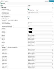
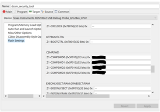
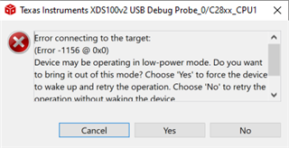
I'm looking to implement a one zone DCSM that protects the memory of the entire device. The preliminary testing is being done on the LAUNCHXL-F28379D. I imported the DCSM Security tool project example from: C2000Ware_4_00_00_00\driverlib\f2837xd\examples\cpu1\dcsm . I updated the sysconfig as shown below and programed the device. It programmed successfully. After the initial program I was unable to program the device again. I put the password in the debug configurations window (shown below), but it still didn't work. I'm getting the error connecting to the target shown below, but when I run the test connection through the target config ccxml, the JTAG DR Integrity scan-test succeeds. I think I'm missing something simple, but I'm not sure what. The design intent is to have all the memory protected on the device once it is released to production. I've looked in the TRM for the device and the DCSM Security Tool app guide, but can't figure out what's wrong.
Hi William,
When you provide the CSM passwords in the On-Chip flash tool and then select "Unlock", does the DSCM unlock successfully?
Thank you,
Luke
No, I've tried through the uniflash program and through CCS & I get the following error:
C28xx_CPU1: Unlocking device... C28xx_CPU1: Error occurred during flash operation: Could not read 0x00078000@Data: target is not connected C28xx_CPU1: Error occurred during flash operation: Could not read 0x00078004@Data: target is not connected C28xx_CPU1: Error occurred during flash operation: Could not read 0x00078008@Data: target is not connected C28xx_CPU1: Error occurred during flash operation: Could not read 0x0005F000@Data: target is not connected C28xx_CPU1: Error occurred during flash operation: Could not read 0x000781F0@Data: target is not connected C28xx_CPU1: Error occurred during flash operation: Could not read 0x000781F2@Data: target is not connected C28xx_CPU1: Error occurred during flash operation: Could not read 0x000781F4@Data: target is not connected C28xx_CPU1: Error occurred during flash operation: Could not read 0x000781F6@Data: target is not connected C28xx_CPU1: Error occurred during flash operation: Could not read 0x000781F8@Data: target is not connected C28xx_CPU1: Error occurred during flash operation: Could not read 0x000781FA@Data: target is not connected C28xx_CPU1: Error occurred during flash operation: Could not read 0x000781FC@Data: target is not connected C28xx_CPU1: Error occurred during flash operation: Could not read 0x000781FE@Data: target is not connected C28xx_CPU1: Error occurred during flash operation: Could not write 0x0005F010@Data: target is not connected C28xx_CPU1: Error occurred during flash operation: Could not write 0x0005F012@Data: target is not connected C28xx_CPU1: Error occurred during flash operation: Could not write 0x0005F014@Data: target is not connected C28xx_CPU1: Error occurred during flash operation: Could not write 0x0005F016@Data: target is not connected C28xx_CPU1: Error occurred during flash operation: Could not read 0x0005F019@Data: target is not connected C28xx_CPU1: Lock status: 1 C28xx_CPU1: Error unlocking device. Device still locked. Please recheck the entered password. C28xx_CPU1: Error occurred during flash operation: Could not write 0x0005F800@Data: target is not connected
Somehow, after I programmed the device, I'm not able to connect to it anymore at all.
Hi William,
Is the device configured to use wait boot or flash boot? If flash boot, you won't be able to connect to the device due to ECSL protection when the flash is secured.
Thank you,
Luke
I was initially running in Emulation Boot, but also tried Wait boot.
I noticed that the dcsm security tool seems to have the wrong address for boot control. TRM shows Z1-BOOTCTRL is 0x7801E while the autogenerated dcsm.cmd file has z1 boot control as 0x7801C. I didn't select the boot control section in the sys config file, so that section of the dcsm.asm file is commented out. I would think that since the dcsm_opt_z1_bootctrl is commented out, this would not have caused a problem. I'm not sure what should be stored at 0x7801C. I'm including the entire dcsm.asm & dcsm.cmd files for reference as well as the conflicting TRM snippet. The only thing changed is the actual password text in the dcsm.asm file.
;---------------------------------------------------------------------- ; Zone 1 ;---------------------------------------------------------------------- .sect "dcsm_otp_z1_linkpointer" .retain .long 0x1FFFFFFF .long 0xFFFFFFFF ;Reserved .long 0x1FFFFFFF .long 0xFFFFFFFF ;Reserved .long 0x1FFFFFFF .long 0xFFFFFFFF ;Reserved .sect "dcsm_otp_z1_pswdlock" .retain .long 0xFFFFFFF0 .long 0xFFFFFFFF ;Reserved .sect "dcsm_otp_z1_crclock" .retain .long 0xFFFFFFFF .long 0xFFFFFFFF ;Reserved ;; .sect "dcsm_otp_z1_bootctrl" ;; .retain ;; .long 0xFFFFFFFF ;Reserved ;; .long 0x49550B5A .sect "dcsm_zsel_z1" .retain .long 0x000000FF ;Z1-EXEONLYRAM .long 0x00003FFF ;Z1-EXEONLYSECT .long 0x10005555 ;Z1-GRABRAM .long 0x05555555 ;Z1-GRABSECT .long 0xPASSWORD .long 0xPASSWORD .long 0xPASSWORD .long 0xPASSWORD ;---------------------------------------------------------------------- ; For code security operation,after development has completed, prior to ; production, all other zone select block locations should be programmed ; to 0x0000 for maximum security. ; If the first zone select block at offset 0x10 is used, the section ; "dcsm_rsvd_z1" can be used to program these locations to 0x0000. ; This code is commented out for development. ; .sect "dcsm_rsvd_z1" ; .loop (1e0h) ; .int 0x0000 ; .endloop ;---------------------------------------------------------------------- ; Zone 2 ;---------------------------------------------------------------------- .sect "dcsm_otp_z2_linkpointer" .retain .long 0x1FFFFFFF .long 0xFFFFFFFF ;Reserved .long 0x1FFFFFFF .long 0xFFFFFFFF ;Reserved .long 0x1FFFFFFF .long 0xFFFFFFFF ;Reserved .sect "dcsm_otp_z2_pswdlock" .retain .long 0xFFFFFFFF .long 0xFFFFFFFF ;Reserved .sect "dcsm_otp_z2_crclock" .retain .long 0xFFFFFFFF .long 0xFFFFFFFF ;Reserved ;; .sect "dcsm_otp_z2_bootctrl" ;; .retain ;; .long 0xFFFFFFFF ;Reserved ;; .long 0x49550B5A .sect "dcsm_zsel_z2" .retain .long 0x000000FF ;z2-EXEONLYRAM .long 0x00003FFF ;z2-EXEONLYSECT .long 0x3000FFFF ;z2-GRABRAM .long 0x0FFFFFFF ;z2-GRABSECT .long 0xFFFFFFFF .long 0xFFFFFFFF .long 0xFFFFFFFF .long 0xFFFFFFFF ;---------------------------------------------------------------------- ; For code security operation,after development has completed, prior to ; production, all other zone select block locations should be programmed ; to 0x0000 for maximum security. ; If the first zone select block at offset 0x10 is used, the section ; "dcsm_rsvd_z2" can be used to program these locations to 0x0000. ; This code is commented out for development. ; .sect "dcsm_rsvd_z2" ; .loop (1e0h) ; .int 0x0000 ; .endloop ;---------------------------------------------------------------------- ; End of file ;----------------------------------------------------------------------
/* this linker command file is to be included if user wants to use the DCSM feature on the device * DCSM means Dual Zone Code Security Module. * This linker command file works as an addendum ot the already existing Flash/RAM linker command file * that the project has. * The sections in the *_ZoneSelectBlock.asm source file is linked as per the commands given in the file * NOTE - please note fill=0xFFFF, this helps if users include this file in the project by mistake and * doesn't provide the needed proper *_ZoneSelectBlock.asm sources . * Please refer to the Blinky DCSM example in the controlsuite examples for proper usage of this. * * Once users are confident that they want to program the passwords in OTP, the DSECT section type can be removed. * */ MEMORY { PAGE 0 : /* Program Memory */ /* Z1 OTP. LinkPointers */ DCSM_OTP_Z1_LINKPOINTER : origin = 0x78000, length = 0x00000C /* Z1 OTP. GPREG1/GPREG2 */ DCSM_OTP_Z1_GPREG : origin = 0x7800C, length = 0x000004 /* Z1 OTP. PSWDLOCK/RESERVED */ DCSM_OTP_Z1_PSWDLOCK : origin = 0x78010, length = 0x000004 /* Z1 OTP. CRCLOCK/RESERVED */ DCSM_OTP_Z1_CRCLOCK : origin = 0x78014, length = 0x000004 /* Z1 OTP. RESERVED/BOOTCTRL */ DCSM_OTP_Z1_BOOTCTRL : origin = 0x7801C, length = 0x000004 /* DCSM Z1 Zone Select Contents (!!Movable!!) */ /* Z1 OTP. Z1 password locations / Flash and RAM partitioning */ DCSM_ZSEL_Z1_P0 : origin = 0x78020, length = 0x000010 /* Z2 OTP. LinkPointers */ DCSM_OTP_Z2_LINKPOINTER : origin = 0x78200, length = 0x00000C /* Z2 OTP. GPREG1/GPREG2 */ DCSM_OTP_Z2_GPREG : origin = 0x7820C, length = 0x000004 /* Z2 OTP. PSWDLOCK/RESERVED */ DCSM_OTP_Z2_PSWDLOCK : origin = 0x78210, length = 0x000004 /* Z2 OTP. CRCLOCK/RESERVED */ DCSM_OTP_Z2_CRCLOCK : origin = 0x78214, length = 0x000004 /* Z2 OTP. GPREG3/BOOTCTRL */ DCSM_OTP_Z2_BOOTCTRL : origin = 0x7821C, length = 0x000004 /* DCSM Z2 Zone Select Contents (!!Movable!!) */ /* Z2 OTP. Z2 password locations / Flash and RAM partitioning */ DCSM_ZSEL_Z2_P0 : origin = 0x78220, length = 0x000010 } SECTIONS { dcsm_otp_z1_linkpointer : > DCSM_OTP_Z1_LINKPOINTER PAGE = 0 dcsm_otp_z1_pswdlock : > DCSM_OTP_Z1_PSWDLOCK PAGE = 0 dcsm_otp_z1_crclock : > DCSM_OTP_Z1_CRCLOCK PAGE = 0 dcsm_otp_z1_bootctrl : > DCSM_OTP_Z1_BOOTCTRL PAGE = 0, type = DSECT dcsm_zsel_z1 : > DCSM_ZSEL_Z1_P0 PAGE = 0 dcsm_otp_z2_linkpointer : > DCSM_OTP_Z2_LINKPOINTER PAGE = 0 dcsm_otp_z2_pswdlock : > DCSM_OTP_Z2_PSWDLOCK PAGE = 0 dcsm_otp_z2_crclock : > DCSM_OTP_Z2_CRCLOCK PAGE = 0 dcsm_otp_z2_bootctrl : > DCSM_OTP_Z2_BOOTCTRL PAGE = 0, type = DSECT dcsm_zsel_z2 : > DCSM_ZSEL_Z2_P0 PAGE = 0 } /* //=========================================================================== // End of file. //=========================================================================== */
Hi William,
Since you're using default boot settings, it's still possible that you've selected flash boot via the boot mode select pins:
Can you make sure GPIO72 and GPIO84 are configured to use wait boot?
Thank you,
Luke
Yes, I used the switches on the launchpad to configure GPIO72 & GPIO 84 to wait boot.
Could you try the following steps and let me know if this works:
Are you still unable to connect after following these steps?
Thank you,
Luke
Yes, after doing that I'm still unable to connect to the device. Is it possible the boot control register not matching between the TRM and the security tool is part of the problem? I'm wondering if I've changed the boot configuration / pins.
Hi William,
The address in the TRM is incorrect, this will be corrected in the next release of the TRM.
Can you try power cycling the device after configuring the wait boot pins and repeating the steps I shared above?
Thank you,
Luke
I have the same problem when I cycle power before trying to connect to the target.
Hi William,
Do you have another device to test with? I'm not sure what could be causing you to not be able to connect based on your DCSM settings. Could you update your C2000Ware to the latest version, program DCSM settings using SysConfig and see if you get the same issue?
Let me loop in a JTAG expert to see if they have any ideas what could cause the debugger to not be able to connect.
Thank you,
Luke
Yes, I have another device to test with, but I was looking to see what could have been my problem before I repeat the same steps and lock myself out of the entire device again.
Hi William,
Understood, I will attempt to recreate this issue on my side using the latest C2000Ware and CCS versions, I'll be back in office on January 6th to test this.
Thank you,
Luke
Hi William,
I think I've recreated the issue on my side. After programming I am able to reconnect but I'm unable to reprogram, I will look into the root cause of this issue and let you know once I have an update.
Thank you,
Luke
Hi William,
I've tested this issue on my side and was successfully able to unlock and reprogram the locked device. Couple of questions:
Did you changed the switches on the launchpad to:
SW1: off
SW2: on
SW3: on
If you're still unable to program, could you modify the GEL file's ECSLUnlock function to use your custom passwords?
Could you make sure the "reset target before flash programming operations" option in the On-Chip flash tool is unchecked before attempting to program?
Thank you,
Luke
I didn't initially have the switches set to Off, on, on, but I did try that when I was trying to reprogram. I'll try again with C2000Ware Version: 5.04.00.00. & CCStudio Version: 20.0.1.
There's no prohibited passwords correct?
As long as you do not set any bits that were a 0 by default to a 1, there are no prohibited passwords. Try to flip 0s to 1s will result in a programming failure anyways.
Also, a password of all 0s will result in the zone being permanently locked.
Make sure to power cycle after adjusting the switches so that the boot mode takes effect.
When I unchecked the "reset target before flash programming" selection, I was able to reprogram the device. I didn't see any ECSL Unlock function in the GEL file. Is that something that I should add?
Hey William,
I don't think that's needed for what you're trying to do. Some devices may not have the ECSL unlock function in the GEL file which is OK. Let me know if you have additional questions.
Thank you,
Luke
By the way, the reason "Reset target before flash programming operations" would've prevented you from programming is because the DCSM always gets re-enabled upon a device reset which would prevent flash programming.
Yeah, that clicked once I saw that. I didn't think about the reset being the default operation when I was working on this, but it definitely makes sense now. Thank you for you help!