This thread has been locked.
If you have a related question, please click the "Ask a related question" button in the top right corner. The newly created question will be automatically linked to this question.
Tool/software:
Hello,
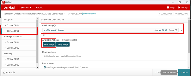
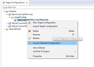
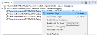
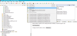
I have develop a application in which i use both CPUs. While debugging code over both CPUs it works fine. but when i try to upload .out file to both CPUs using uniflash, CPU2 doesn't run code. Please let me know if there is any specific procedure to follow. What i am doing currently is I load corresponding .out file in C28xx_CPu1 and C28xx_CPU2 and then press load image button in both tabs one by one. Please let me know where i am doing mistake.
Hi Kashyap,
Is the device in Flash boot mode after the load has completed?
Thanks and regards,
Charles
Hello Charles,
Sorry for the late reply. I’m still new to working with TMS320 and dual-core controllers, so I’ve been trying to figure out how to set this up. From my hardware schematic, I found that GPIO 72 and GPIO 84 are connected to other input pins. I’m not sure if both pins are set to 1 during a CPU reset. Is there another way to handle this?
Hi Kashyap,
GPIO 72/84 is configured to be pulled high/low externally by the boot switches, assuming you haven't programmed the OTP.
Are you attempting to load to a LaunchPad, ControlCard, etc? Is CPU1 running code successfully?
Best,
Matt
Hello Mr. Matt,
Thank you for you reply,
I have not programmed OTP. I am using TMS320 on my my PCB. While i try to debug both CPUs work simultaneously but when i flash out file on both CPU. only CPU1 runs perfectly. But CPU2 doesn't work properly. I have a board developed for my application.
I have updated my board to pull GPIO 72 and GPIO 84 high problem is still continue. Please let me know if I am making any mistake in loading image on controller.
Regards,
Kashyap.
Hi Kashyap,
I appreciate the clarification, it helps out a lot :)
The GPIOs only set the boot mode for CPU1. It sounds like CPU2 is not booting to the application in flash and is in wait boot. With no boot programmed, CPU2 will go to wait boot in which it waits for the CPU1 application to send IPC commands to boot to flash or RAM (see 4.10.8 in the TRM).
I suggest trying the examples in C2000Ware to see how that is done:
Besides using IPC commands to configure CPU2 boot, you can either configure the EMU_BOOTCTRL registers for CPU2 and emulate the standalone mode with debugger connected, or program the OTP for CPU2 to boot to flash upon boot. As the OTP can only be programmed once, I recommend you test using the emulation registers first to confirm functionality.
Best,
Matt
Hello,
As it's been several weeks without a reply, I'll assume this question has been resolved and close the thread.
Best,
Matt
Hello Matt,
Sorry for not replying. Due to project urgency I was busy in other work, I will try it asap and will revert.
Regards,
Kashyap Vasani.
Hello Kashyap,
No worries, if you have any questions or concerns feel free to reach out on this thread.
Best,
Matt
Hello Matt,
I have gone through section 4 of technical reference manual. As per best of my understanding I have placed
HWREG(0x0005F004) = 0x00000B5A;
HWREG(0x0005F044) = 0x00000B5A;
in starting of void main() of CPU2 but still doesn't seem working. What I was trying to do was to set CPU2 in flash boot mode. so CPU2 starts as soon as controller is powered up or reset it CPU2 also get boot up. Please let me know where i have mistaken?
Hi Kashyap,
Please write your configurations to the BOOTCTRL registers in the OTP Flash (0x7801E/0x7821E). Here are the register locations in memory per the TRM:
You can also try using the DCSM tool (in the SysConfig CPU2 context) or the On-Chip Flash tool in CCS (Connect to CPU2 > Tools > On-Chip Flash) to configure the boot configurations. If you have not looked at this application note, it details how to use the DCSM security tool: https://www.ti.com/lit/pdf/spracp8
Lastly, I'll also note there's no need to program the Z1 and Z2 OTP registers, as Z2 supersedes the Z1 configurations. I'd advise you to program Z1 first, then Z2.
Best,
Matt
Hello Matt,
Sorry for asking very basic questions. Please check below image, if this is what you were talking about?
Regards,
Kashyap.
Hey matt, I tried making that value 0X00000B5A. but still result is same if you need any part of my code or any screenshot please let me know.
Thank you for keeping up with me.
Best Regards,
Kashyap
Hi Kashyap,
Yes, that is the correct register.
What location in the flash are you loading the CPU2 application? What is the state of CPU2 after boot?
Best,
Matt
Hello Matt,
I am loading my out file in uniflash and directly pressing load image button. is there any setting need to be done?
Regards,
Kashyap Vasani
Hi Kashyap,
That looks correct. How are you verifying that CPU2 is not booting to flash? Are you loading the boot ROM symbols to verify the state of CPU2?
You can step through the device boot ROM by loading the boot ROM symbols (.out file) to the device. This option adds the symbols available in the generated project '.out' file for debugging purposes instead of loading the actual '.out' program onto the core via CCS - this is also why you can use this method with the boot ROM/built in bootloaders to debug and get visibility.
Best,
Matt
Hi Matt,
I am very new for dual core processers and also TI controllers. So, I don't know what is symbols and how it works. honestly I didn't get whatever you have said in last reply. Can you please suggest some tutorial or videos to get basics. so, I can understand every terminology you are using.
also, Another thing has happened after OTP memory writing experiment that I am able to program my CPU1 using CCS flash tool but when I am loading it with uniflash it didn't work. also, even if i have it loaded with CCS flash tool still after power cycle it stops working.
Thanks and regards,
Kashyap
Hi Kashyap,
Have you looked at the Boot ROM chapter in the Technical Reference Manual? This provides the most comprehensive information on how the boot flow works on F2837xD devices, including the CPU2 boot flow.
I also highly suggest searching other E2E posts about CPU2 booting. There is a lot of helpful information that may be relevant and hopefully answer your questions.
So, I don't know what is symbols and how it works.
At the simplest level symbols are metadata in compiled code (binaries) that contain information about functions and global data (global variables and read-only data) in the file. Usually a symbol contains a name, address and size. Loading the boot ROM symbols into CCS allows you to view the boot ROM as you're debugging.
also, Another thing has happened after OTP memory writing experiment that I am able to program my CPU1 using CCS flash tool but when I am loading it with uniflash it didn't work. also, even if i have it loaded with CCS flash tool still after power cycle it stops working.
What's not working ie. what error message is UniFlash providing?
Best,
Matt
Due to having no reply in a month, I will be closing this thread and assume the issue is resolved.