LAUNCHXL-F280039C: Issues with Level 4 in Universal Lab Motor Control - LAUNCHXL-F280039C & BOOSTXL-3PhGanInv + Teknic_M2310PLN04K

Part Number: LAUNCHXL-F280039C
Other Parts Discussed in Thread: BOOSTXL-3PHGANINV

Tool/software:

Dear TI Support Team,

I am currently working with the LAUNCHXL-F280039C paired with the BOOSTXL-3PhGanInv module to control a  motor using the Universal Motor Control Labs firmware at LEVEL 4.

After successfully completing all the previous levels, I encountered some strange behavior when running the motor at LEVEL 4.

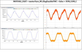
I’ve attached a figure with graphs from both DATALOG and oscilloscope waveforms for better visualization. These graphs were generated using motor_datalog_fp2.graphProp from <install_location>\solutions\universal_motorcontrol_lab\common\debug.

Measurement Setup:

  • Phase currents (IA) were measured on the IA pin of the BOOSTXL-3PhGanInv.
  • Phase voltages (VA) were measured on the VA pin.
  • For simplicity, the attached figure is structured as a table with three columns:
    1. Firmware Level.
    2. Graphs from Code Composer Studio (CCS).
    3. Corresponding Oscilloscope Waveforms.

Test Setup:

  • Both Sensorless FAST and Encoder methods were tested.
  • PWM frequency: 45 kHz.
  • Motor speed: 100 Hz.
  • Various settings for timers, filters, and motor parameters are included in the attached user_mtr1.h file for completeness.

Observations and Questions:

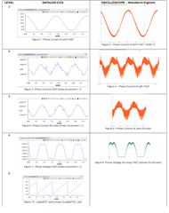
  1. Non-Sinusoidal Currents in Level 4:
    In LEVEL 3 (open-loop), the current waveforms are perfectly sinusoidal, as shown in Figures 1 and 2. However, at LEVEL 4, during motor startup, the current waveform is sinusoidal but becomes distorted when the motor reaches the set speed (Figures 3–6).
    Why do the current waveforms lose their sinusoidal shape in LEVEL 4?

  2. FAST vs. Encoder Differences:
    Figures 3, 4, 5, and 6 clearly show differences in the current waveforms between FAST and Encoder. For example, the distortion visible in Figure 4 (FAST) is different from Figure 6 (Encoder).
    What could be causing this difference between FAST and Encoder?

  3. Phase Voltage Offset:
    Comparing the phase voltage measurements (VA) in Figures 7, 8:

    • Figures 7  (ADC measurements) show a noticeable negative offset.
    • Figure 8 (oscilloscope measurement) does not show this offset.
      Despite following the offset correction procedure in LEVEL 1, this issue persists.
      What could explain the negative offset in the ADC measurements?

I would greatly appreciate your insights on these issues to help me resolve the distortion in the current waveforms. Please let me know if further information is required.

Thank you for your support!

Marco Lasagni

2117.user_mtr1.h

  • Marco,

    Thank you for the in-depth question and pertinent background information, that's very helpful.

    For build level 4, note that the startup process includes an initial open-loop phase, where motor feedback is not considered- based on the information provided, this is likely why the current begins sinusoidal but loses that shape.

    My first thought for the source of your issues is that the Teknic motor you're using is somewhat off from the one used when choosing parameter values, and this is causing the motor feedback to be incorrectly interpreted. Slight distortions are then of course magnified in a closed loop system.

    Lastly, for the datalog tool vs oscilloscope differences, I'd recommend opening the CCS expressions window and looking at the voltage values there. If the voltage values in the expressions window match the oscilloscope measurements, then there's a scaling issue with the datalogger. If the voltage values match the datalog graph, then this is likely related to the rest of the distorted values you're seeing.

    Debug questions:

    1. If you run the Motor ID process and use the resulting values for InstaSPIN-FOC FAST, does the behavior persist?

    2. When looking at the voltage values in the CCS expressions window, do the values you see there match those of the datalog graph or the oscilloscope readout?

    3. Is the motor rotating smoothly? i.e. no vibrations, etc. that would indicate significant alignment or parameter issues

    Please let me know the results of the Motor ID test, and if this does not fix the problem, please address the other questions as well.

    Regards,
    Jason Osborn

  • Hi Jason,

    Thank you for your detailed response.

    Even after performing the Motor ID process, with parameters that turned out to be nearly identical to the default values, the behavior remains unchanged, and the current waveform is still highly distorted.

    We are using exactly the same Teknic motor referenced in the Universal Lab and other TIDAs that rely on circuits similar to those of the BOOSTXL-3PhGaNInv.

    For now, I’d like to focus on fixing the current waveform distortion. What do you think? Do you have any other suggestions or ideas?

    Best regards,
    Marco

  • For now, I’d like to focus on fixing the current waveform distortion.

    Hi Marco, 

    In addition to Jasons comments can you verify the debug script shows the correct full modulation mode eQEP encoder enabled? Check code (motor_common.c) three places should be enabled and motor1_drive.c line 339 also, motorVars_M1.flagEnableFWC = false displayed CCS debug monitor. The scope and DAC voltage, current captures (encoder enabled) look as if the control mode is SVM_MIN_C. Make sure project general symbols have both FAST, ESMO symbols enabled. BTW: FOC level 3 is the control mode (encoder_n), FAST with ESMO are the estimator library functions. Seemingly FWC mode checks SVM_MIN_C true for half wave or full wave forms depending on DCLINKSS optional board attached.

    #if !defined(MOTOR1_ISBLDC)
    SVGEN_setMode(obj->svgenHandle, SVM_COM_C);
    #endif //! MOTOR1_ISBLDC

    Fullscreen
    1
    2
    3
    4
    5
    6
    7
    8
    9
    10
    11
    12
    13
    14
    15
    16
    17
    // Patched code:
    /* Motor ID use SVM_COM_C */
    //if(objUser->flag_bypassMotorId == true)
    if(motorVars_M1.flagEnableFWC == true && objUser->flag_bypassMotorId == true)
    {
    #if defined(MOTOR1_DCLINKSS)
    obj->svmMode = SVM_COM_C;
    #else // !(MOTOR1_DCLINKSS)
    obj->svmMode = SVM_MIN_C;
    #endif // !(MOTOR1_DCLINKSS)
    obj->flagEnableFWC = true; //was true
    }
    else
    {
    obj->svmMode = SVM_COM_C;
    obj->flagEnableFWC = false;
    }
    XXXXXXXXXXXXXXXXXXXXXXXXXXXXXXXXXXXXXXXXXXXXXXXXXX

  • Hi,

    thank you for the post.

    I have a few clarifications regarding your request:

    1. Debug Script Verification:

      • In motor1_drive.c, at line 339, I found:  EQEP_enableModule(obj->qepHandle);
        This seems to enable the eQEP module, but I’m unsure what I should check three times in motor_common.c. Could you clarify what I need to look for?
    2. motorVars_M1.flagEnableFWC Behavior:

      • In the code this flag was set to true.
      • Disabling it didn’t cause any noticeable changes.
    3. Scope & DAC Captures (Voltage/Current Acquisition):

      • At startup, the control mode is initially SVM_COM_C, but then it switches to SVM_MIN_C.
      • I did observe a slight improvement in performance after set MotorVars_M1.svmMode = SVM_COM_C  (as shown in the attached data).
    4. Clarification on SVM_Mode_e:
      Could you explain the differences in usage between the following modes?

      typedef enum {
      SVM_COM_C = 0, //!<
      SVPWM common SVM mode SVM_MIN_C = 1, //!< DPWM minimum SVM mode
      SVM_MAX_C = 2, //!< DPWM maximum
      SVM SVM_DQ_S = 3 //!< SVPWM standard DQ mode
      } SVM_Mode_e;
      • When should each mode be used?
      • How do they affect modulation and motor control performance?
    5. Clarification about Patched code you posted
    6. Current Sensing Configuration note:

      • The current sensing is right set as systemVars.currentSenseType = CURSEN_TYPE_INLINE_SHUNT;

    Thanks for your help!

    Best,

    Marco Lasagni

  • Hi Marco,

    Please review the universal motor LAB guide PDF found in universal documents folder path. That will explain most all your remaining questions. 

    The current sensing is right set as systemVars.currentSenseType = CURSEN_TYPE_INLINE_SHUNT;

    Only for inverters with inline shunts or three low-side current shunt depends on type of inverter being used.