TMS320F28379S: Issue with Serial Flash Programming using SCI Bootloader example from C2000ware

Part Number: TMS320F28379S
Other Parts Discussed in Thread: C2000WARE,

Dear Texas Instruments Support Team,

                                        I'm currently working on implementing SCI bootloader using example F2837xS_SCI_Flash_kernel from C2000ware.

Issue -   While trying to upload code using command in terminal. After "adjusting port settings" in terminal  the process is not proceeding further which provides me a options for selecting DFU(Device Firmware Update).

Hardware Setup:


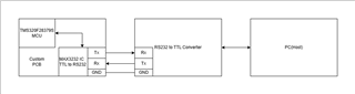
- Custom PCB with TMS320F28379S.
- RS232 Out from the TMS320F28379S is connected to an RS232-to-USB converter,
which is then connected to the PC via a USB port.

Steps Followed:
1. Uploaded SCI Flash Kernel:
- I uploaded the F2837xS_SCI_Flash_kernel code to the micro controller using the XDS110 Debugger.

2. Prepared Application Code:
- I prepared an application code for a simple LED blink.
- Converted the application code to .txt format using `hex2000` via the command line.

3. Ran the Serial Flash Programmer Command:

serial_flash_programmer_appln.exe -d f2837xS -k F2837xS_sci_flash_kernel.txt -a LED_blink.txt -b 115200 -p COM9
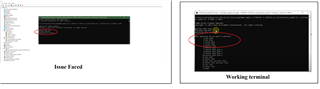
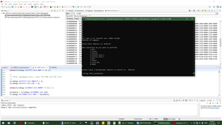
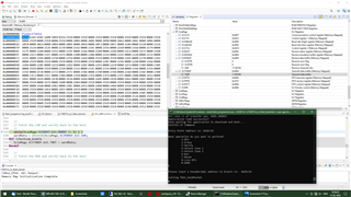
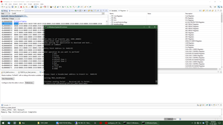
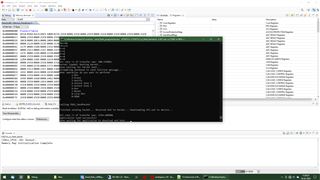
Terminal Output:

getting comm state
building comm DCB
adjusting port settings

After this, the process doesn't proceed further. Which gives me an option to select DFU.

Things I’ve Tried So Far:
1. Checked the COM Port:
- Verified that the RS232-to-USB converter is correctly connected and recognized as COM9 in Device Manager.

2. Checked Boot Mode of the Micro controller:
- Confirmed the GPIO pins for SCI Boot Mode are configured correctly.


- Could anyone suggest what might be causing this issue?
- What further steps can I take to troubleshoot and resolve this issue?

Thanks in advance for any assistance!

  • Hi,

    Some suggestions:

    - If you wish to use SCI boot mode with standalone load of the kernel, you should use the serial_flash_programmer.exe 

    - Check that your GPIOs are set appropriately for SCI communication

    - What GPIOs are the kernel communicating with?

    Thanks,

    Charles

  • Hi Charles,

    • SCI Boot Mode & Serial Flash Programmer
      I’ve tried using the "serial_flash_programmer.exe" as you suggested, but the issue remains the same. Additionally, I also experimented with a reduced baud rate, but that didn’t resolve the problem either.

    • GPIOs for Boot mode
      The boot mode is set to SCI, with GPIO 72 set to 0 and GPIO 84 set to 1 for SCI communication.

    • SCI Communication pins
      I’ve verified both the code and hardware for the SCI pins (GPIO 28 and 29), and everything seems to be in order. I also confirmed that SCI communication works when tested with terminal software.

      Kindly suggest how can i proceed further.

      Thanks

  • Hi,

    This is likely due to a GPIO mismatch. GPIO 28 and 29 are used for the alternate GPIO pins, with GPIO 84 and 85 as defaults. Is it possible for you to:

    1) Set the device in EMU boot mode for GPIO 28 and 29

    2) Run the CPU1 target in CCS and then use the "serial_flash_programmer.exe" along with the arguments used:

    serial_flash_programmer.exe -d f2837xS -k F2837xS_sci_flash_kernel.txt -a LED_blink.txt -b 115200 -p COM9

    If you wish to use GPIO 84/85 which is being used by this mode, then you have to edit the flash kernel for these GPIO selections in project's source files.

    Thanks,

    Charles

  • Hi,

        Kindly explain about the GPIO missmatch.

    1.In hardware I've connected  GPIO pin 72 and 84  as shown in datasheet for SCI mode.For 1 i've connected to 3.3v and for 0 I connected to gnd.

    2.In example code i've selected pin 28 and 29 as shown below since pin 84 belongs to Boot mode control pin

    3.As per datasheet GPIO pin 72 and 84 are boot control pins. How come can I set EMU boot mode for GPIO 28 and 29.

  • Hi,

    The device boot ROM by default uses GPIO 84 and 85 for SCI communication.

    You can set the EMU boot mode for GPIO 28 and 29 as well. Can you try loading with the EMU boot mode set for GPIO 28 and 29, the Boot Mode Select pins need not be considered since the device would be connected through JTAG in CCS.

    Thanks and regards,

    Charles

  • Hi Charles,

    I tried the steps you suggested but am still facing some issues:

    1. I am using GPIO 28 and 29 for SCI bootloader.
    2. Initially, I connected the XDS110 to the controller.
    3. I set to debug mode, ran the code, and then went to the registers tab.
    4. I tried modifying the Z1_BOOTCTRL register as shown in the screenshot.
    5. When I entered 0x5A810010 to set the mode and pressed Enter, the value did not change.
    6. Another method, I tried modifying the specific register in expression window,the value didn't changed.

    Could you please confirm is my procedure right? and if ok kindly suggest how to proceed.

    Thanks!

  • What was your reduced or current baudrate? 

    I should add that to enter the emulation boot mode for this device, it is explained in section 7.3.2 of the Serial Flash Programming of C2000 Microcontrollers application note. 

    0xD00 location should contain the value 0x815A in the Memory browser.

    Z1_BOOTCTRL values can only be modified by programming the OTP through the Flash API, and is not necessary is you wish to succeed doing emulation mode only at first.

  • Hi,
    I followed the steps mentioned below but am facing an issue at the end:


    1.I went to debug mode from the SCI_Flash_kernel example code in Code Composer Studio.
    2.I paused the operation and opened the memory browser.
    3.In the memory browser, I searched for 0x1D00 and updated the first element to 0x815A.


    4.I then did RUN -> CPU Reset.
    5.I pressed the Play button.
    6.I ran the command from the command prompt.

    "serial_flash_programmer.exe -d f2837xS -k F2837xS_sci_flash_kernel.txt -a LED_Blink.txt -b 115200 -p COM9"

    7.The flash kernel got dumped.
    8.I selected option 1 for DFU.


    9.The application code got dumped and asked for next step ,I selected option 6  to run.


    10.It then asked for the address to branch to.
    11.I copied the entry point address from above and pasted it below.

    12.The process gets stuck at “calling f021_SendPacket.”

    How can I solve this issue?

    I also tried this method by setting the SCI boot mode using the GPIO pins, but it didn't work either. Kindly suggest how can I proceed further.

  • Could you load the symbols for the kernel when it is running through CCS? This way we can see closer what happens with the SendPacket function.

  •  

    Hi Charles,

    Even though the process gets stuck at “calling f021_SendPacket”, I was able to verify that my application code was successfully uploaded to Flash via SCI by resetting the controller.

    However, my main concern is that when using SCI boot mode without Emulation Boot Mode, the process does not proceed beyond the first transmission.

    When running the following command in the terminal:

    "serial_flash_programmer.exe -d f2837xS -k F2837xS_sci_flash_kernel.txt -a ups-gpio.txt -b 9600 -p COM9"  
    

    The process stops at:

    "calling f021_DownloadKernel CPU1 Kernel  
    Downloading F2837xS_sci_flash_kernel.txt to device...  
    aa  "
    

    It does not continue further.

    Steps Followed:

    1. Used the F2837xS_SCI_Flash_Kernel example code from C2000Ware and modified it to use alternate pins for SCI communication.
    2. Uploaded the modified code using CCS.
    3. Connected the SCI pins of the MCU to the PC.
    4. Ran the command.
    5. However, the process did not proceed beyond the first transmission.

    Could you help me resolve this issue?

  • Rajamurugan,

    Please see section table 4-24 of the TMS320F2837xS Real-Time Microcontrollers Technical Reference Manual (Rev. I). The default GPIOs for TX/RX are 84 and 85 in boot ROM.

    When you load the kernel through GPIOs 28+29 using emulation boot, you manually override this setting by modifying the value stored at 0xD00. This is not persistent through a power reset. To change it permanently, you must set the OTP BMODE value to 0x81 as listed in the table.

    An alternative option is to use GPIOs 84 and 85.

    Best,

    Alex

  • Hi Alex,

                 I am facing an issue regarding SCI boot mode when using alternate pins.

    Issue: When using SCI boot mode with alternate pins (after modifying the example code), the process does not proceed beyond the first transmission—it gets stuck at that point.

    Steps I Followed:
                                   1.Modified the example code "F2837xS_SCI_FLASH_KERNEL" from C2000Ware to work with alternate pins as shown below:
                                                              In F2837xS_sci_flash_kernel.c, I updated the code to:
                                                               "EntryAddr = SCI_GetFunction(SCI_BOOT_ALTERNATE);"

                                   2.Uploaded the code using CCS (I didn't performed any power reset after this).

                                   3.Connected the SCI pins of the MCU to the PC.

                                    4.Ran the following command:

                                                                "serial_flash_programmer.exe -d f2837xS -k F2837xS_sci_flash_kernel.txt -a ups-gpio.txt -b 9600 -p COM9" 

                                    5.However, the process did not proceed beyond the first transmission

                                                                 "calling f021_DownloadKernel CPU1 Kernel
                                                                   Downloading F2837xS_sci_flash_kernel.txt to device...
                                                                   aa"

    1.Do I need to set OTP BMODE value if yes how to set that value. 

    2.Another concern is if I need to use the default 84 and  85 pin as you suggested How come I change the default boot mode selection pin which is 84 and 72 to some other value. For example how do  I change the Boot mode selection pin from 72 and 84 to 3 and 2.

    My ultimate thing is to 1st set the Boot selection pin to sci mode and upload firmware then set the Boot selection pin to flash mode to always boot from flash when firmware update is needed I can physically change them to sci mode .

    Kindly help me to resolve this issue

  • Rajamurugan,

    You can change either the boot mode select pins or the SCI pins so that they don't conflict, both require programming OTP. This can be done using the Flash API. To change and/or configure the boot select pins, refer to TMS320F2837xS Real-Time Microcontrollers Technical Reference Manual (Rev. I) section 4.5, and to change the SCI pins see section 4.10.6.

    As for your current issue, this occurs even when using emulation boot correct? Can you confirm the kernel is running on the device? After loading through CCS, can you pause the program and check if it is in autobaud?

    Best,

    Alex

  • Hi Alex,

    No, while working with emulation boot mode, everything works well until the last step. When I select the DFU option, the application code gets loaded, and I am prompted for the next step. I select option 6 to run.

    It then asks for the address to branch to. I copy the entry point address from above and paste it as required.

    At this point, the process gets stuck at "calling f021_SendPacket."

    Even though the process doesn't complete, when I reset the MCU, it successfully boots from flash and runs the application code. So, this issue only occurs when I dump the code using the XDS110 debugger and follow the steps mentioned previously(Modifying code as mentioned above)

    Kindly help me to solve why it is not going beyond first transmission.

    I also have another question: :- Mean time I've decided to use GPIO 3 and 2 for Boot mode select pin instead of 72 and 84 to avoid conflict during SCI operation.

     Is there any detailed example code or application note available for changing the boot mode select pins by programming the OTP?

  • Rajamurugan,

    Can you enable verbose mode by adding the "-v" option when calling the host programmer?

    Best,

    Alex

  • Hi Alex,

    Yes I can enable verbose mode by adding "-v" at end. I have attached image of the result

    During my 1st attempt it stuck at 1st transmission and during my second attempt there was an error with autobaud lock echo back. 

    And Kindly share If there is  any detailed example code or application note available for changing the boot mode select pins by programming the OTP?

  • Rajamurugan,

    There are not any example projects for programming the boot mode select pins, the best reference would be the flash programming examples, which you can modify to write the to the desired OTP ranges. The TMS320F2837xS Flash API Reference Guide (Rev. A) will also be helpful in doing this.

    I am still working on replicating this and will hopefully have a more in-depth response tomorrow or early next week.

    I would also like to ensure that I am understanding correctly, and that you are seeing two separate issues:

    • When using emulation boot (no power reset, load the kernel through CCS), the kernel hangs on calling f021_SendPacket
    • When booting from SCI (after power reset), the device fails to autobaud when uploading the kernel and afterwards hangs. The point at which it fails is not consistent

    Best,

    Alex

  • Hi Alex,

    When using emulation boot (no power reset, load the kernel through CCS), the kernel hangs on calling f021_SendPacket

    Your understanding of this issue is correct.

    But,

    For this

    When booting from SCI (after power reset), the device fails to autobaud when uploading the kernel and afterwards hangs. The point at which it fails is not consistent

    I did boot from sci but before that I uploaded the modified code using ccs to assign alternate pins for sci.

    I used below mentioned steps

     1.Modified the example code "F2837xS_SCI_FLASH_KERNEL" from C2000Ware to work with alternate pins as shown below:
                                                              In F2837xS_sci_flash_kernel.c, I updated the code to:
                                                               "EntryAddr = SCI_GetFunction(SCI_BOOT_ALTERNATE);"

                                   2.Uploaded the code using CCS (I didn't performed any power reset after this).

                                   3.Connected the SCI pins of the MCU to the PC.

                                    4.Ran the following command:

                                                                "serial_flash_programmer.exe -d f2837xS -k F2837xS_sci_flash_kernel.txt -a ups-gpio.txt -b 9600 -p COM9" 

                                    5.However, the process did not proceed beyond the first transmission

                                                                 "calling f021_DownloadKernel CPU1 Kernel
                                                                   Downloading F2837xS_sci_flash_kernel.txt to device...
                                                                   aa"

    Hope this helps and I appreciate the assistance here Thanks!

  • Rajamurugan,

    For the second issue (the autobaud one), try using serial_flash_programmer_appln.exe. This version only sends the app over SCI, as the kernel has already been placed in RAM by CCS.

    I am still looking into the first issue.

    Best,

    Alex

  • Hi Alex,

    Could you kindly help me with this?

    I tried the steps you mentioned, and the application successfully loads to Flash. However, the kernel hangs at f021_SendPacket, which is the same issue observed in emulation mode.

    I am currently working on implementing the Flash API to change the Boot Mode Select Pins.

    BMSP0: Changing from GPIO 84 to GPIO 73
    This will allow me to use the default SCI boot mode pins (GPIO 84, GPIO 85) for firmware updates.

    Final Requirement:
    Under normal operation, the MCU should always boot from Flash.
    When a firmware update is needed, I will set the Boot Mode Select Pins to SCI mode, update the firmware, and then set them back to Flash mode.
    After a power reset, the MCU should always boot from Flash unless manually set to SCI mode for an update.

    Major Concern:
    As per my understanding, if I correctly configure the Boot Mode Select Pins , I should be able to successfully load the kernel and application code using serial_flash_programmer.exe.
    without the need of using JTAG and CCS?

    Could you please confirm if my approach is correct?

  • Rajamurugan,

    Yes, if the GPIOs and boot mode are properly configured and selected, you will be able to load both the kernel and application code over SCI.

    Can you try lowering the baud rate under 100K?

    If that doesn't work, can you load the kernel through CCS and go through the normal loading process up until f021_SendPacket, then pause the kernel in CCS. Where is it getting stuck?

    Best,
    Alex

  • Hi Alex,

    Yes, if the GPIOs and boot mode are properly configured and selected, you will be able to load both the kernel and application code over SCI.

    I need modify"BMSP0: Changing from GPIO 84 to GPIO 73"   but before modification(writing to OTP) is there any ways to check its working in emulation boot mode.

    If yes suggest how to do.


    Can you try lowering the baud rate under 100K?

    I tired with baud rate 9600,19200 results are same no improvements in error

    If that doesn't work, can you load the kernel through CCS and go through the normal loading process up until f021_SendPacket, then pause the kernel in CCS. Where is it getting stuck?

    Then as suggested I've uploaded the kernel code using CCS in debug mode to play and pause code 

    The I ran the below mentioned command

    "serial_flash_programmer_appln.exe -d f2837xS -k F2837xS_sci_flash_kernel.txt -a ups-gpio.txt -p COM8 -b 19200 -v"

    When the process hangs at f021_SendPacket I paused the code and the result I've attached in below image 

    Kindly do the needful

  • Rajamurugan,

    To test your OTP configuration, see section 4.5 and table 4-6 of the TMS320F2837xS Real-Time Microcontrollers Technical Reference Manual (Rev. I). In addition to emulating the boot mode, you can also test boot mode select pin changes.

    After f021_SendPacket, can you try sending a second run command (type 6, then Enter)? If that doesn't do anything, can you show the contents of the SCI TX and RX buffers (can be found in the registers view).

    Best,

    Alex

  • Hi Alex,

    Sorry for the delayed response

    Below is the screenshot of the contents of SCI TX and RX buffer as requested.

  • Rajamurugan,

    I was finally able to recreate this issue today and will try and find a solution soon. In the meantime, could you share a picture of your call stack?

    Best,

    Alex

  • Hey Rajamurugan,

    Can you try inserting a no-op at the bottom of the while loop in the function SCI_GetFunction in SCI_GetFunction.c?

    The resulting code snippet will look like:

    Fullscreen
    1
    2
    3
    4
    5
    6
    7
    8
    9
    10
    11
    12
    //
    // Send the packet and if NAK send again.
    //
    while(SCI_SendPacket(command, statusCode.status, 12,
    (Uint16*)&statusCode.address, statusCode.flashAPIError,
    (Uint16*)&statusCode.flashAPIFsmStatus))
    //
    // Get next Packet
    //
    __asm(" NOP");
    command = SCI_GetPacket(&length, data); //get next packet
    XXXXXXXXXXXXXXXXXXXXXXXXXXXXXXXXXXXXXXXXXXXXXXXXXX

    Best,

    Alex

  • Hi Alex,

    I tried what you have suggested output found to be satisfied. Below I've attached my output.

    However I'm facing some issue while using my real application code above steps were done using a simple led blink code.

    Here I've attached my screenshot for your reference.

    Kindly help me out on how to proceed.

  • Rajamurugan,

    Could you confirm whether or not the sections (mapped to the flash) in the linker command file are aligned using ALIGN(8)?  If not, can you please align them?

    Best,

    Alex

  • Hi Alex,

    Below are the modifications I made in code correct me if I'm wrong

    Fullscreen
    1
    2
    3
    4
    5
    6
    7
    8
    9
    10
    11
    //28379S_FLASH_lnk.cmd
    //Line numbers mentioned below
    0: .cinit : > FLASHB PAGE = 0, ALIGN(8)
    81: .pinit : > FLASHB, PAGE = 0, ALIGN(8)
    82: .text : >> FLASHB | FLASHC | FLASHD | FLASHE PAGE = 0, ALIGN(8)
    83: codestart : > BEGIN PAGE = 0, ALIGN(8)
    95: PAGE = 0, ALIGN(8)
    105: PAGE = 0, ALIGN(8)
    115: .econst : >> FLASHF | FLASHG | FLASHH PAGE = 0, ALIGN(8)
    116: .switch : > FLASHB PAGE = 0, ALIGN(8)
    XXXXXXXXXXXXXXXXXXXXXXXXXXXXXXXXXXXXXXXXXXXXXXXXXX

    Output is not as expected the application code is not loaded in flash.

    process hangs as shown below 

  • Rajamurugan,

    That linker file looks good. Are you passing the .out or the .txt image to the host programmer as your application? The host programmer and kernel expect the application to be in a certain ASCII format which must be generated using a post-build step. More information on this can be found in Serial Flash Programming of C2000 Microcontrollers (Rev. H) section 3.

    Best,

    Alex

  • Hi Alex,

    By mistake I used .out file instead of .txt file.

    Now it works good.

    I need another help regarding programming OTP memory

    I tried EMU boot mode to test change in BMSP

    I tried using 0xFE5A for 0xD00 and 0x004A for 0xD01 but it is not working.

    My requirement is to set BMODE to SCI and  BMSP0 to 73 

  • Rajamurugan,

    Apologies, I was mistaken earlier, and emulation of the boot mode select pins is not available on this device, you will have to program the OTP region.

    The BOOTCTRL register is located at address 0x7801E and should be programmed with the following words: 0x5A0B 0x4948 0xFE5A 0x0049. This will set BMSP0 = GPIO73, BMSP1 = GPIO72, and the default boot mode as read the boot mode select pins.

    Please note that the Flash API has a 64-bit minimum when programming in order to properly compute the ECC value, so your buffer might need to include some of the surrounding memory.

    Best,

    Alex

  • HI Alex,

    Can you try inserting a no-op at the bottom of the while loop in the function SCI_GetFunction in SCI_GetFunction.c?

    Even though the command ends without any hang ,but code is not running from flash after this step 

    Kindly help me on this

  • Rajamurugan,

    Does the LED blinky example also fail to run after the command ends?

    Also, I saw your earlier response (not sure where it went) and you are correct -- there are registers for emulating the boot mode select pins. 

    Try using 0xD00 = 0xFE5A, 0xD01 = 0x0049.

    Best,

    Alex

  • Hi Alex,

    Yes The LED Blinky example also fails to run.


    I have successfully emulated the BMSP by using value FE5A and 004A , but my doubt are

    1.What value I need to write to  Z1_BOOTCTRL in OTP using on chip menu in debug.

    As per result from EMU boot mode the value is  0x004A 0B5A 

    But I noticed the default was 0xFFFFFFFF so as per this I assume the value would be 0xFF4A 0B5A 

    Kindly let me know the correct value, so that I can try programming the OTP memory


    Kindly Let me know the solution for why it is failing to run and the correct  value for register.

  • Hi Rajamurugan,

    I see you have two on-going threads discussing the same topics. I'm going to close the other thread and address your questions on this thread.

    But I noticed the default was 0xFFFFFFFF so as per this I assume the value would be 0xFF4A 0B5A 

    That is not correct. Since you require BMSP0 = GPIO73 and BMSP1 = GPIO72, then you want to keep the BOOTCTRL configuration as 0x004A 0B5A. The '00' will keep BMSP1 in its default configuration (GPIO72), but 'FF' will set it to GPIO255.

    Try using 0xD00 = 0xFE5A, 0xD01 = 0x0049

    This configuration will have the device read the emulation BMSPs, but use the boot mode (if programmed) in the OTP BOOTCTRL register when GET mode is picked.  

    1.What value I need to write to  Z1_BOOTCTRL in OTP using on chip menu in debug.

    You will need to program 0x004A 0B5A into Z1-BOOTCTRL to configure BMSP0=GPIO73, BMSP1=GPIO72, and BMODE=Boot to Flash. You can then boot the device to Flash by enabling GET mode (setting BMSP0 and BMSP1 both to 1).

    Best,

    Matt

  • Hi Matt,

    Thanks for the response! 

    I successfully used 0x004A 0B5A it's working good as expected.

    Does the LED blinky example also fail to run after the command ends?

    But this issue still persist Kindly provide solution for this issue.

  • Hi Rajamurugan,

    Looking at your application's linker command file, it seems like you're placing it in FlashB ie. 0x082000. However, the Flash boot (0x0B) entry point address is 0x80000. For the device to successfully boot to your application, then you need to put the application at the Flash entry point 0x80000.

    Best,

    Matt

  • Hi Matt,

    Fullscreen
    1
    2
    3
    4
    5
    6
    7
    8
    9
    10
    11
    12
    13
    14
    15
    16
    17
    18
    19
    20
    21
    /*Exsisting*/
    /* Flash sectors */
    FLASHA : origin = 0x080002, length = 0x001FFE /* on-chip Flash */
    FLASHB : origin = 0x082000, length = 0x002000 /* on-chip Flash */
    /* Allocate program areas: */
    .cinit : > FLASHB PAGE = 0, ALIGN(8)
    .pinit : > FLASHB, PAGE = 0, ALIGN(8)
    .text : >> FLASHB | FLASHC | FLASHD | FLASHE PAGE = 0, ALIGN(8)
    codestart : > BEGIN PAGE = 0, ALIGN(8)
    /* Initalized sections go in Flash */
    .econst : >> FLASHF | FLASHG | FLASHH PAGE = 0, ALIGN(8)
    .switch : > FLASHB PAGE = 0, ALIGN(8)
    /*Modified*/
    XXXXXXXXXXXXXXXXXXXXXXXXXXXXXXXXXXXXXXXXXXXXXXXXXX

    Here I have attached my existing and modified piece of code.


    Is this correct ? or do I need to make some other changes.

    I tried this and its not working as required.

    1.Kindly provide some detailed insights and steps.

    2.And for the info I haven't made any changes to linker file so by default it goes to FLASH B right? so in future I need to make all these changes to make SCI bootloader work or is there is anything I can do while configuring initially. 

  • Hi,

    Did you also modify the codestart (BEGIN) to 0x80000? If so, please send me your .map file for the build so I can see where the application is being loaded.

    2.And for the info I haven't made any changes to linker file so by default it goes to FLASH B right? so in future I need to make all these changes to make SCI bootloader work or is there is anything I can do while configuring initially. 

    Can you re-clarify this? I'm not sure I understand completely.

    Best,

    Matt

  • Hi matt,

    Can you re-clarify this? I'm not sure I understand completely

    I haven't changed the linker file, so by default, the code is placed in FLASH B, right?

    In the future, do I always need to modify the linker file for the SCI bootloader to work, or is there a way to configure it correctly from the start?

    Did you also modify the codestart (BEGIN) to 0x80000? If so, please send me your .map file for the build so I can see where the application is being loaded.

    Yes the codestart (BEGIN) was set to 0x80000

    Fullscreen
    1
    2
    3
    4
    5
    6
    7
    8
    9
    10
    11
    12
    13
    14
    15
    16
    17
    18
    19
    20
    21
    ******************************************************************************
    TMS320C2000 Linker PC v22.6.1
    ******************************************************************************
    >> Linked Thu Mar 27 09:02:30 2025
    OUTPUT FILE NAME: <ups-gpio.out>
    ENTRY POINT SYMBOL: "_c_int00" address: 00082c99
    MEMORY CONFIGURATION
    name origin length used unused attr fill
    ---------------------- -------- --------- -------- -------- ---- --------
    PAGE 0:
    RAMM0 00000122 000002de 00000000 000002de RWIX
    RAMLS0 00008000 00000800 00000072 0000078e RWIX
    RAMLS1 00008800 00000800 00000000 00000800 RWIX
    RAMLS2 00009000 00000800 00000000 00000800 RWIX
    RAMLS3 00009800 00000800 00000000 00000800 RWIX
    RAMLS4 0000a000 00000800 00000000 00000800 RWIX
    RAMD0 0000b000 00000800 00000000 00000800 RWIX
    XXXXXXXXXXXXXXXXXXXXXXXXXXXXXXXXXXXXXXXXXXXXXXXXXX
     

    This is my .map file hope these information helps

    Kindly help me out with this issue.

  • Hi,

    I haven't changed the linker file, so by default, the code is placed in FLASH B, right?

    In the future, do I always need to modify the linker file for the SCI bootloader to work, or is there a way to configure it correctly from the start?

    As long as your application's codestart is at 0x0008 0000, then the application should be successfully booted to. You map file confirms this is case and the generic flash linker command file is setup to do that already, so no need to modify in the future.

    I didn't know if this was the case because the linker command file snippets you provided omitted where the codestart was and only showed where the application was being loaded.

    I tried this and its not working as required.

    And when you say the application is not working, do mean when booting to flash on reset? Or after the serial_flash_programmer is finished programming the application.

    Best,

    Matt

  • Requirement:- Need to run application code after completion of commands through sci bootloader

    And when you say the application is not working, do mean when booting to flash on reset? Or after the serial_flash_programmer is finished programming the application.

    After all commands from Serial_flash_programmer is finished the application code fails to run. Only works when I switch to get mode and reset the mcu.


    DO you need any other information for debugging?

    Kindly provide solution to my issue.

  • Hi,

    After all commands from Serial_flash_programmer is finished the application code fails to run. Only works when I switch to get mode and reset the mcu.

    After you execute "1-DFU" in the serial_flash_programmer, do you do "6-Run" and specify the entry point of the application?

    Best,
    Matt

  • Hi matt,

    Yes I use RUN command and specify the entry point 

    I have already mentioned the steps I performed in the discussion above. Could you please review the full conversation and address my issue accordingly?

    Let me know if you need any specific details.

    9.The application code got dumped and asked for next step ,I selected option 6  to run.
    10.It then asked for the address to branch to.
    11.I copied the entry point address from above and pasted it below.
  • Rajamurugan,

    What address does the device branch to after receiving the run command? Does this only occur when branching to the application from the kernel, or also when booting from flash? Can you verify the contents of flash against your .out file using the C2000 Flash Utility "Verify Only" function?

    Best,

    Alex

  • Hi Matt,

    Below, I've explained my issue for your clarification.

    Setup: Initially, I changed the boot mode select pin using the on-chip flash tool in debug mode so that we could use the default SCI pins for the bootloader.

    Issue: After completing the bootloader process, the RUN command executes successfully, but the application code does not run (it is not transitioning from the kernel to the application code).

    What address does the device branch to after receiving the run command?

    The Entry point address is 0x82c9a for code with FLASHA set 

    The Entry point address is 0x82d21 for code with FLASHB set 

    Does this only occur when branching to the application from the kernel, or also when booting from flash?

    This issue occurs only when branching to application from kernel.

    When booting from flash it's working good.

    Can you verify the contents of flash against your .out file using the C2000 Flash Utility "Verify Only" function?

    I can confirm that the code works as expected when booted from flash after a reset.

    Could you please provide the steps to use the C2000 Flash Utility to verify with my .OUT file ?

    Is there anything else I need to clarify? Please compile all necessary details in one response so I can work on them in a single day and get back to you quicker.

    Thanks for assisting. I look forward to your response soon.