This thread has been locked.

If you have a related question, please click the "Ask a related question" button in the top right corner. The newly created question will be automatically linked to this question.

TMS320F28388D: Clarification on ISR Behavior in Multi-core Setup

Other Parts Discussed in Thread: TMS320F28388D
  1. Part Number: TMS320F28388D

Tool/software:

Hi Team,

In my current implementation, I have the same two interrupt sources configured for each core:

  • CPU1: ADC ISR1, eCAP1
  • CPU2: ADC ISR1, eCAP1

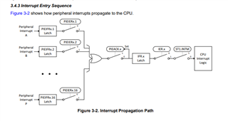
Both cores are triggered by the respective ISRs, but the code executed on each core differs. The ePWM module initiates the ADC Start-of-Conversion (SOC), and upon completion of the ADC conversion, ADCINT1 triggers interrupts on both cores. The PWM timer period is approximately 39 µs.

Additionally, once every line cycle, an eCAP interrupt is generated and also triggers both cores. I've captured the interrupt waveforms using GPIOs that toggle at the entry and exit points of each ISR, and the results are shared below.

For testing purposes, I added extra computations inside the eCAP1 ISR that extend beyond the PWM interrupt period.

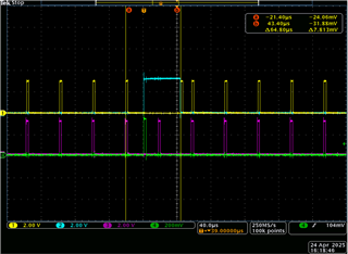
Waveform Channel Mapping:

  • Ch1: CPU1 ADC ISR
  • Ch2: CPU1 eCAP ISR
  • Ch3: CPU2 ADC ISR
  • Ch4: CPU2 eCAP ISR

1.Normally, the ADC ISR is triggered every 39 µs. However, if the eCAP ISR gets serviced before the ADC ISR, the ADC ISR execution is delayed until the eCAP ISR completes.

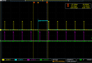
2.In one scenario, the eCAP ISR completes just before the next ADC ISR, leaving only a small window for ADC ISR execution on CPU1.

3.In another case, the eCAP ISR doesn't leave enough time, resulting in one ADC ISR being skipped. My question is: why did CPU2 also skip the ADC ISR in this scenario?

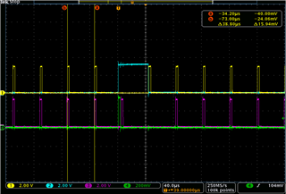
I suspect that since the ADC peripheral is owned by CPU1, it is responsible for clearing the interrupt flag. If CPU1 does not clear the flag, the ADC ISR won’t trigger again. However, once CPU1 executes the next ADC ISR and clears the flag, CPU2 should be able to respond to the ADC interrupt as well.

My queries are:

  1. What conditions can lead to both CPU1 and CPU2 missing the ADC ISR under these circumstances?
  2. Is it possible for a peripheral (like ePWM or ADC) owned by one core to trigger an ISR on the other core without triggering it on its own core, considering the interrupt flag cannot be cleared by the non-owning core?
  3. Given that the eCAP ISR has the lowest priority, is it a valid approach to use simple nesting (enabling/disabling interrupts using EINT and DINT like below) inside the eCAP ISR to ensure the ADC ISR always gets executed?

__interrupt void ecap3ISR(void)
{
    if (ECap3Regs.ECFLG.bit.CEVT1 == 0x1)
    {
        ECap3Regs.ECCLR.bit.CEVT1 = 0x1;
    }
    if (ECap3Regs.ECFLG.bit.CEVT2 == 0x1)
    {
        ECap3Regs.ECCLR.bit.CEVT2 = 0x1;
    }
    if (ECap3Regs.ECFLG.bit.CEVT3 == 0x1)
    {
        ECap3Regs.ECCLR.bit.CEVT3 = 0x1;
    }
    if (ECap3Regs.ECFLG.bit.CEVT4 == 0x1)
    {
        ECap3Regs.ECCLR.bit.CEVT4 = 0x1;
    }
    PieCtrlRegs.PIEACK.all = PIEACK_GROUP4;
    ECap3Regs.ECCLR.bit.INT = 0x1;
    
    EINT;
    
    /* some code
    */
    
    DINT;
}

4. One final question on interrupt nesting: If I want an ePWM interrupt to preempt an eCAP ISR (from a different interrupt group), what are the steps to enable that? TI’s documentation covers nesting within the same group, but not across groups.

Are there risks in allowing eCAP to be nested by ePWM? I want to avoid a scenario like eCAP1 -> EINT -> eCAP2 -> EINT -> ePWM, where two eCAP ISRs delay the higher-priority ePWM ISR. My goal is to minimize latency and ensure ePWM isn't delayed by back-to-back eCAPs.

  • Hello,

    I apologize for my delayed response. Below are my responses to your questions:

    • What conditions can lead to both CPU1 and CPU2 missing the ADC ISR under these circumstances?

    To clarify, you are only clearing the ADC flag on the CPU1 ISR, is that correct? In that case, I believe this does explain the behavior you are seeing. The interrupt trigger will initially be sent from the ADC to both CPUs simultaneously. At this moment, CPU1 is still executing the eCAP ISR, so the ADC ISR won't execute until the eCAP ISR is complete. Note that multiple interrupts coming in from the same source won't build up, so if another trigger is sent from the ADC by this time when the previous one is pending, it will still only execute the ISR once (as can be seen in the waveform). CPU2 is able to execute the ADC ISR immediately, so it does, however it doesn't clear the ADC flag since it doesn't have ownership. When the next trigger comes in from the ADC, there is no actual level change of the (0 to 1) flag so the PIE on CPU2 does not get any interrupt, and the CPU1 is executing it interrupt from before that was blocked.

    One way to avoid this would be to put the ADC into continuous mode so that the flag isn't actually required to be cleared in the ISR to receive further interrupts. This would use the bit field here:

    Is it possible for a peripheral (like ePWM or ADC) owned by one core to trigger an ISR on the other core without triggering it on its own core, considering the interrupt flag cannot be cleared by the non-owning core?

    Technically you could disable the ADC ISR manually inside of the eCAP ISR and re-enable it in the main or somewhere when you are ready to start getting interrupts on CPU1 again. For this approach you would need to somehow have CPU2 signal CPU1 when it's done with its ISR using IPC, I wouldn't recommend this approach since it would be more complicated.

    Given that the eCAP ISR has the lowest priority, is it a valid approach to use simple nesting (enabling/disabling interrupts using EINT and DINT like below) inside the eCAP ISR to ensure the ADC ISR always gets executed?

    Yes, that would indeed be valid in this case (assuming these are the only two interrupts enabled on CPU1). Just remember that CPU1 would still need to go back and finish executing the eCAP ISR after it is done with the nested ADC ISR. There would be some added ISR execution times due to the extra branching between ISRs. The nested ADC ISR will have more delay between the trigger and execution than a regular ADC ISR that comes in.

    One final question on interrupt nesting: If I want an ePWM interrupt to preempt an eCAP ISR (from a different interrupt group), what are the steps to enable that? TI’s documentation covers nesting within the same group, but not across groups.

    I would suggest taking a look at my first reply on this thread: (+) TMS320F28388D: EINT and Nesting - C2000 microcontrollers forum - C2000Tm︎ microcontrollers - TI E2E support forums. It covers how to implement all of the different nesting scenarios. The one in particular you are asking about would be under "Simple Nesting" Case 1.

    Are there risks in allowing eCAP to be nested by ePWM? I want to avoid a scenario like eCAP1 -> EINT -> eCAP2 -> EINT -> ePWM, where two eCAP ISRs delay the higher-priority ePWM ISR. My goal is to minimize latency and ensure ePWM isn't delayed by back-to-back eCAPs.

    This case would still be "Simple Nesting" Case 1. With this implementation, the sequence you outlined would not happen since the ACK would still be open for the eCAP interrupt group; the eCAP ISR's would not be able to nest each other. Only the ePWM interrupt can nest inside the lower group priority eCAP ISRs.

    Please upvote this response if it was helpful to youSlight smile

    Best Regards,

    Delaney

  • Thanks for the detailed explanation. Could you please confirm the following points:
    1. Multiple interrupts from the same source do not queue up – If an ADC interrupt is triggered while a previous ADC interrupt is still executing, the new one will be skipped? Also, if I clear the ADC interrupt flag and acknowledge it at the start of the ISR, will that terminate the current interrupt and allow the newly triggered one to run instead?
    2. One more observation: I have both EPWM and ADC interrupts, and I've assigned EPWM ownership to CPU2. When using the emulator, if I start CPU1 first and then CPU2, the EPWM interrupt not running. The interrupt seems to enter CPU1 (which is not the owner) and never reaches CPU2. However, if I start CPU2 first and then CPU1, the EPWM interrupt works as expected on both CPUs.
    Is there any dependency on the order in which the CPUs are started when using the emulator? For context, in CPU1’s main() function, I configure the EPWM module first, then after an IPC sync, I assign ownership to CPU2. I boot CPU2 from CPU1, and only afterward do I reassign the EPWM module to CPU2.
  • Hi Yedida,

    1. A correction here: You would be able to get another interrupt from the same spot in the PIE if it comes in when servicing a previous ISR. You just would not be able to service more than one since there is only one latch. What I mentioned previously is the case of losing an interrupt if getting a second ADC ISR when the previous one is still pending, not while its being executed. The case I was talking about was if you get two ADC ISRs when the eCAP ISR is executing. In this case only one would be executed after the eCAP ISR. 

    It helps to think of it in hardware: the PIE can only send one interrupt to the CPU at a time and there is only one PIEIFR latch in the circuit for each interrupt. When an ISR is entered, the INTM switch is opened and the ACK for the current group is opened. If more than one interrupt from a peripheral come in during this time, the latch for those PIEIFR's will still just be high (there is no indication in the PIE of how many have come in).

    If you just clear the ADC flag and close the group ACK, the INTM bit would still be blocking further interrupts since this opened automatically everytime an ISR is executed. I would only suggest following the code in one of the scenarios from the link I provided, any other code could cause unexpected behavior. 

    2. When you say "started using the emulator" do you mean connecting to the target, loading the .out or pressing Resume in CCS. Can you outline the order you are doing each of these steps for both cores? We do have some documentation on how this should be done: 6. Debugging multiple cores — C2000Tm Multicore Development Guide

    Best Regards,

    Delaney

  • Thank you for the detailed explanation.
    2. I connected to the DSP using the XDS220 emulator and followed the procedure provided in the link. My question is: when I change the ePWM core assignment and the order of CPU2 booting, it seems to affect the behavior. First time interrupt entering the CPU1 but not the CPU2 hence interrupt flag not get cleared. As a result, no further ePWM interrupts are triggered. However, the code works as expected when I change the order—first assigning the core to ePWM and then booting CPU2 and some in-between statements . 
    Could you clarify if there are any precautions we need to take regarding the sequence of CPU2 booting, core assignment, IPC sync, and interrupt enabling?
  • Latest Observation:

    ePWM configuration done in cpu1 and later assigned ownership to cpu2.

    I connected to 28388D through xds220 emulator. I have connected to cpu1 and load the out file and then connected to cpu2 and loaded the out file. both cpus are in supended mode like the image below.

    Running the cpu2 first using the highlighted button,

    Code in CPU1

    void main(void)
    {
        //
        // Initializes device clock and peripherals
        //
        Device_init();
    
         InitGPIO();
    
        //
        // Initialize PIE and clear PIE registers. Disables CPU interrupts.
        //
        Interrupt_initModule();
    
        //
        // Initialize the PIE vector table with pointers to the shell Interrupt
        // Service Routines (ISR).
        //
        Interrupt_initVectorTable();
    
         //
        // Give memory access to GS0 and GS7 RAM to CPU1
        //
        MemCfg_setGSRAMControllerSel((MEMCFG_SECT_GS0 | MEMCFG_SECT_GS1 |
                                      MEMCFG_SECT_GS2 | MEMCFG_SECT_GS3 |
                                      MEMCFG_SECT_GS4 | MEMCFG_SECT_GS5 |
                                      MEMCFG_SECT_GS6 | MEMCFG_SECT_GS7),
                                 MEMCFG_GSRAMCONTROLLER_CPU1);
    
        //
        // Give memory access to GS8 to GS15 RAM to CPU2
        //
        MemCfg_setGSRAMControllerSel((MEMCFG_SECT_GS8 | MEMCFG_SECT_GS9 |
                                      MEMCFG_SECT_GS10 | MEMCFG_SECT_GS11 |
                                      MEMCFG_SECT_GS12 | MEMCFG_SECT_GS13 |
                                      MEMCFG_SECT_GS14 | MEMCFG_SECT_GS15),
                                 MEMCFG_GSRAMCONTROLLER_CPU2);
    
        initADC();
    
        initEpwm(&EPwm6Regs);
    
        EPwm6Regs.ETSEL.bit.INTSEL = ET_CTR_ZERO;     // Select INT on Zero event
        EPwm6Regs.ETSEL.bit.INTSELCMP = 0;
        EPwm6Regs.ETSEL.bit.INTEN = 1;                // Enable INT
        EPwm6Regs.ETPS.bit.INTPRD = ET_1ST;           // Generate INT on 3rd event
    
        EPwm6Regs.ETSEL.bit.SOCASEL = ET_CTR_ZERO;
        EPwm6Regs.ETSEL.bit.SOCASELCMP = 0;
        EPwm6Regs.ETPS.bit.SOCAPRD = ET_1ST;
        EPwm6Regs.ETSEL.bit.SOCAEN = 1;
    
    
    	//ecap & Other epwm intializations
    
    	// CAN & I2C initialization
    
    
        initVariables();
    
                             //
        // Hand-over the CAN module access to CPU2
        //
        SysCtl_selectCPUForPeripheral(SYSCTL_CPUSEL0_EPWM, 5, SYSCTL_CPUSEL_CPU2);
        SysCtl_selectCPUForPeripheral(SYSCTL_CPUSEL0_EPWM, 6, SYSCTL_CPUSEL_CPU2);
        SysCtl_selectCPUForPeripheral(SYSCTL_CPUSEL0_EPWM, 7, SYSCTL_CPUSEL_CPU2);
        SysCtl_selectCPUForPeripheral(SYSCTL_CPUSEL0_EPWM, 8, SYSCTL_CPUSEL_CPU2);
        SysCtl_selectCPUForPeripheral(SYSCTL_CPUSEL11_ADC, 1, SYSCTL_CPUSEL_CPU2);
    
        //
        // Boot CPU2 core
        //
        #ifdef _FLASH
            Device_bootCPU2(BOOTMODE_BOOT_TO_FLASH_SECTOR0);
        #else
            Device_bootCPU2(BOOTMODE_BOOT_TO_M0RAM);
        #endif
    
    
    //       Flgs.Flt_Flgs1.Node_ID_Initalization_Fail_Flg = FALSE;
    
        InitCLA();
    
        // Clear any IPC flags if set already
        //
        IPC_clearFlagLtoR(IPC_CPU1_L_CPU2_R, IPC_FLAG_ALL);
    
        //
        // Synchronize both the cores.
        //
        IPC_sync(IPC_CPU1_L_CPU2_R, IPC_FLAG31);
    
        Interrupt_register(INT_EPWM6, &epwm6ISR);
        Interrupt_register(INT_ECAP1, &ecap1ISR);
        Interrupt_register(INT_ECAP2, &ecap2ISR);
        Interrupt_register(INT_ECAP3, &ecap3ISR);
        Interrupt_register(INT_ECAP4, &ecap4ISR);
    
        Interrupt_enable(INT_EPWM6);
        Interrupt_enable(INT_ECAP1);
        Interrupt_enable(INT_ECAP2);
        Interrupt_enable(INT_ECAP3);
        Interrupt_enable(INT_ECAP4);
    
        // Enable Global Interrupt (INTM) and realtime interrupt (DBGM)
        //
        EINT;
        ERTM;
    
    	//while(1) function
    }
    

    Code in CPU2

    void main(void)
    {
        //
        // Initialize device clock and peripherals
        //
        Device_init();
    
    
        //
        // Initialize PIE and clear PIE registers. Disables CPU interrupsampleTime.
        //
        Interrupt_initModule();
    
        //
        // Initialize the PIE vector table with pointers to the shell Interrupt
        // Service Routines (ISR).
        //
        Interrupt_initVectorTable();
    
    
        //
        // Clear any IPC flags if set already
        //
        IPC_clearFlagLtoR(IPC_CPU2_L_CPU1_R, IPC_FLAG_ALL);
    
        //
        // Synchronize both the cores.
        //
        IPC_sync(IPC_CPU2_L_CPU1_R, IPC_FLAG31);
    
     //   EPwm6Regs.ETCLR.bit.INT = 1;
        //
        // Interrupts that are used in this example are re-mapped to
        // ISR functions found within this file.
        //
        Interrupt_register(INT_EPWM6, &epwm6ISR);
        Interrupt_register(INT_ADCA1, &adcAISR);
    
         //
        // Enable EPWM1 Interrupt
        //
        Interrupt_enable(INT_EPWM6);
        Interrupt_enable(INT_ADCA1);
        //
        // Enable Global Interrupt (INTM) and realtime interrupt (DBGM)
        //
        EINT;
        ERTM;
        //
        // Loop forever. Wait for IPC interrupt
        //
        while(1)
        {
            scheduleEvents();
        };
    }

    Case 1: If I run cpu2 first and later cpu1 then there is no issue with pwm6 ISR (Its entering in both the CPUs), as it is entering the cpu2 and EPwm6Regs.ETFLG.bit.INT getting cleared so its repeating based epwm TBPRD. 

    Case 2: If I run cpu1 first and later cpu2 then pwm6 ISR is entering in CPU1 but not entering CPU2 because of that EPwm6Regs.ETFLG.bit.INT not getting cleared. So epwm interrupt not generating in any of the CPUs.

    I observed below modifications to tun the interrupt in both the cpus.

    If I add the below statement after IPCsync before enabling the interrupt in CPU2 then no issue, Interrupt is executing as desired in both the cpus.
    “EPwm6Regs.ETCLR.bit.INT = 1;” 

    If adjust the position of ePWM6 assignment to the cpu2 core and cpu2 booting in cpu1 main function, then also working.
     I found the workaround, but I didn’t understand why it’s happening, can you explain what’s the reason behind interrupt not running above case and working when I start with cpu2 irrespective of code?

  • Hello,

    Delaney is currently out of office. Please expect a delay in response until her return next week. 

    Thanks & Regards,

    Allison

  • Hi Allison,

    Thanks for the update.

  • Hi Yedida,

    It sounds like what you are seeing is just based on different timings of your system due to which version of the code you're using. Since only one core can actually clear the flag to cause future interrupts, you need to make sure the ISR operation on the two cores are synchronized.

    Note that according to the TRM, with the ETFLG interrupt, "No further interrupts will be generated until the flag bit is cleared. Up to one interrupt can be pending while the ETFLG[INT] bit is still set. If an interrupt is pending, it will not be generated until after the ETFLG[INT] bit is cleared."

    Can you take a look at the thread linked here which has a similar implementation and synchronizes the operation of the two ISRs?

    Best Regards,

    Delaney

  • Hi Delaney,

    Thanks for the update.

    That link information doesn't solve my issue.

    Can you tell why case 2 not working and but case1 is fine? Why the order of booting is creating dependency?

    What do you mean by version of code can cause this? 

  • Hi Yedida,

    I apologize for the delay. It looks like there is something off with your synchronization of the two cores. 

    ISR is entering in CPU1 but not entering CPU2 because of that EPwm6Regs.ETFLG.bit.INT not getting cleared

    I believe Case 2 isn't working because if CPU1 starts running first, it will initialize the peripheral, enable interrupts and enter the ISR all before CPU2 has enabled the ISR. If the ISR is triggered on CPU2 before CPU2 is running, it won't go to the ISR and will never clear the flag, as you've said. 

    By "version of code" I was just referring to this statement:

    If I add the below statement after IPCsync before enabling the interrupt in CPU2 then no issue, Interrupt is executing as desired in both the cpus.
    “EPwm6Regs.ETCLR.bit.INT = 1;” 

    This version of the code will make sure that the interrupt is definitely triggered on CPU2 after CPU2 has started running and has interrupts enabled. Which will in turn clear the flag at the end of the ISR and enabled further interrupts.

    Can you try moving the  IPC_sync(); calls in both of the initialization code (for CPU1 and CPU2) to be right before EINT? This should make sure the cores will get the first interrupt and branch to the ISRs at the exact same time.

    Best Regards,

    Delaney

  • I tried that before and it worked. Thanks