This thread has been locked.

If you have a related question, please click the "Ask a related question" button in the top right corner. The newly created question will be automatically linked to this question.

FOC Waveforms

Hi,

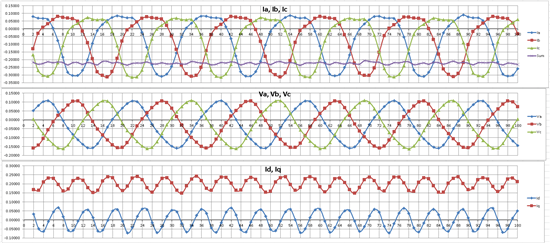
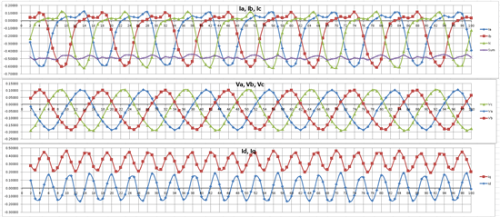
I am running a BLDC/PMSM motor with FOC and am getting strange behavior from the Id and Iq parameters. The first image below is at speed 1, and we can see the bEMF waveforms Va, Vb, Vc look sinusoidal-ish (perhaps slightly triangular). The signals Ia, Ib, Ic are currents through each phase shunt resistor. The references are Id = 0 and Iq = 0.2, but as we can see, they are not steady - they oscillate with each commutation. This gets even worse with references Id=0, Iq=0.35 at speed 2. All units are in per-unit.

My observations/questions:

1) The phase voltages are not centered around 0V, however experiments have shown me that this doesn't affect the oscillation in Id and Iq.

2) I have played with torque loop PI tuning until the cows came home but this had little effect on the oscillation in Iq and Iq; I believe they only effect behavior over longer time spans.

3) Are the shunt resistor current waveforms more or less the expected shape? I believe it may be the very shape of these waveforms that is causing Id and Iq to vary so much with each commutation. Since this is quite a high current application (>100A) I have tried measures to reduce noise on the current sense signals but with only some reduction in Id and Iq oscillation amplitude.

4) Could the oscillation in Id and Iq be due to the motor itself not being 'sinusoidal enough' for the modulation scheme?

Speed 1:


Speed 2:

Any thoughts or suggestions would appreciated.

Thanks.

  • Ken,

    I am going to move this to the C2000 forum that can better assist you. 

  • A couple of things on the graph immediately draw attention to themselves, the voltage and current waveforms have negative offsets on them, is this actual or a measurement/signal processing error? Either way the Park/Clarke calculations will be affected  Also the sum of the current waveforms is not zero suggesting it is more likely to be measurement error, how are you offsetting the bipolar signal pre-ADC and applying the offset to the result.

    I once had an issue with a sinusoidal Id and Iq result and it was caused by a phase current measurement being inverted at the transducer end, but this doesn't look quite the same. What does it look like if you run it open loop (i.e. Id and Iq controllers disabled?)

  • Hi Steve, thanks for your reply.

    While the actual motor phase currents I agree should sum to zero, what I am actually measuring is the current through the low-side shunt resistors. If these summed to zero, it would mean that there is no net current flowing back to the battery and that the motor is not consuming any power. So, I expect to see an offset on the sum of these signals, representative of the net current flow. This offset when converted from pu to Amps, very closely matches the average current I am measuring from the battery using a current clamp (within 4%). The calculated Iq however is underestimating the net current, as shown for example in speed 2 where the I_sum = -0.5 (not sure if the polarity is an issue) but the average Iq is only 0.35. Perhaps the algorithm that is calculating Id and Iq is applying the incorrect offset to the signals.

    In terms of measurement, the current sense amps are biased to 1.65V and the ADCs have a measurement range of 0 - 3.3V. After the ADCs are sampled, the S/W applies an offset (these can be user-set or the S/W can measure these during the start-up procedure) to centre the waveforms properly but I am now wondering if it is not doing this correctly. The clarke/park part of the S/W is a black box where I can't view the code but I can control inputs and view outputs. I experimented by manually adjusting the current offsets to put them way off, but strangely this had no effect on calculated Iq and Id, so it appears as though the black box is compensating with its own internal offsets. As you mentioned, adjusting the offsets of the current and voltage waveforms should have an impact on the calculated Iq and Id.

    It is an interesting idea to run open loop - I may try this.

    Thanks.


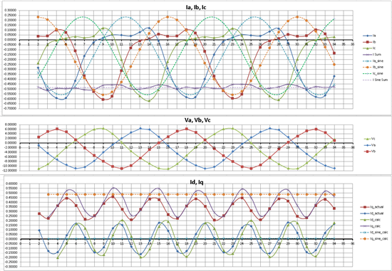
  • I made an interesting discovery that sheds some light on the problem. Entering the formulae for calculating Id and Iq from Ia, Ib and Ic into Excel, I can get fairly close to what the S/W is calculating for Id and Iq. On the bottom graph, purple/green are based on my calculations using Ia, Ib, Ic as inputs, and red/blue are the outputs from the S/W running on the motor controller.

    Now here is where things get interesting. Ideally, I want to see a ripple-free Iq = 0.48 (equal to the average motor current in solid purple on the top graph), and a ripple-free Id = 0. The required input wavforms Ia, Ib and Ic to achieve this are shown in the top graph in dotted lines, which are sinusoidal with an offset. The Iq and Id for these inputs are in orange and light blue respectively in the bottom graph, and they perfectly meet the goal. It took quite a bit of tweaking to get the sinusoids just right, but it shows how my current sense signals differ from what they *should* look like.

    So, my question is: If my bEMF (Va,Vb,Vc) waveforms are so nice and sinusoidal, how can my current sense waveforms be so non-sinusoidal? 

    Are the current sense amplifier circuits the only possible culprits?

    Ken.

  • Do you have a hall effect current sensor or oscilloscope probe so you can look at the actual phase currents? They should match the back-emf waveforms.

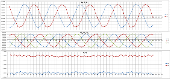
  • I made a big discovery today that the problem is in fact my current sense amps. Using different amp circuits gave me a nice sinusoidal current waveform, and quite flat Id and Iq. Thanks for the help.

  • Ken,

    Can you elaborate on the amps you were using and what you moved to?  I would certainly like to understand this in order to help other customers. 

    Thanks!

  • Hi Ken,

    I have the same problem with my FOC that I have developed.
    Could you explain how it vould be fixed?

    Best regards,
    Chris
  • Hi Krzysztof,
    This post is quite old. You will be more likely to get a response if you create a new post (feel free to include a link to this post if your issue is very similar). It would probably be a good idea to provide the specifics of the problem you are seeing as well.