
- Ask a related questionWhat is a related question?A related question is a question created from another question. When the related question is created, it will be automatically linked to the original question.
Hi
I'm using for the first time MotorWare. Also I'm trying to test for he first time the TMDSHVMTRINSPIN kit. I have a few questions.
-Where I can find the pdf that shows the circuit board connection for my device and for my kit. Does these PDFs exist? And the info in the USB that came with my device has old software and PDF-documents for MCUs which do not correspond.
In MotoroWare is a Quick Start Guide, not clear at all.
All this can be found in MotorWare->InstaSPIN_MOTION->Piccolo F2806xM->GUI ->GUI QSG
Which range do you have in mind for low voltage -high voltage and low current- high current?
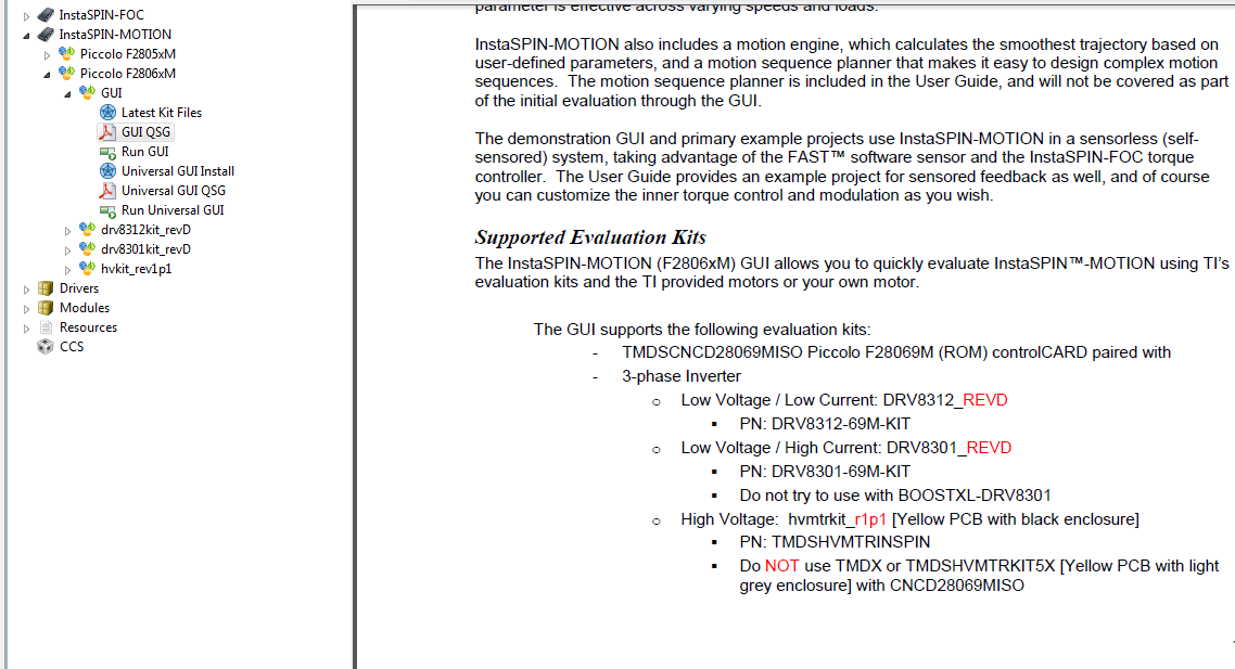
- I couldn't find the meaning of the next setting:
This last two lines. Give me no idea of what they talk about.
...to be clear they should be using the prefix Main or M1 or M2, etc. That is what I noticed in different PDFs.
If I'm using AC Input, do I need to plug the 15V dc eliminator?
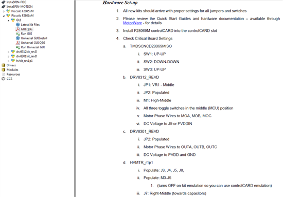
There are many other jumpers already installed, how can I know if they are in the correct position?
I hope you can help me,
Regards Uriel Peláez.


