
- Ask a related questionWhat is a related question?A related question is a question created from another question. When the related question is created, it will be automatically linked to the original question.
This thread has been locked.
If you have a related question, please click the "Ask a related question" button in the top right corner. The newly created question will be automatically linked to this question.
I was just doing some more testing of the motorware software and came across something I don't fully understand. When running my motor with a load (propeller) and I command a reasonably large step change lab11 will sometimes fail, but lab10a works fine. By failure I mean the motor makes a horrible squealing noise then the driver faults.
For example, stepping from 2400rpm to 3750rpm will more often than not cause a fault in lab11. In this case I am powering the board with a bench supply with the current limiter set at 20A and about 130,000uF of extra bulk capacitance. If I switch over to using a battery with no extra capacitance it works 100% of the time but failures still occur with larger step sizes. When a failure does occur I can observe a very ugly voltage transient on the supply rail.
Doing the same testing with lab10a the failure never occurs, even when commanding changes from very low speed to full speed. The transients measured on the supply rail are MUCH less extreme than the fault case of lab11. I plotted the RPM (measured externally) vs time for both labs and found the response to be identical. In my application it is critical to have rapid response to changes in commanded speed.
I know that lab11 is missing the trajectory controller. In lab10 I have MaxAccel_krpmps set to 32. Is the lack of the trajectory control the root of the problem in lab 11, or is there some other factor? Maybe something like slew rate control on the current loops?

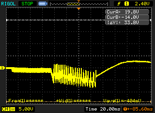
The voltage transient is different. Attached is a plot of a transient during a fault.
The thicker portion that starts halfway through the first division I see in all cases. The really ugly stuff that starts around the 4th division I don't see when there is no fault. At around 7.5 is I think where it gives up (undervoltage fault) and the motor coasts to a stop. In this case this is AC coupled 5v/div
I also confirmed this problem is not present in lab11a.

Nominal voltage is 15v, but I am using the LAUNCHXL-F28027F+BOOSTXL-DRV8305 setup. The problem is NOT present in lab11a.
I think this is related to overmodulation issues. lab 11 does not have any of the overmodulation changes, as 11a does. Try the attached document, where I got 11 and added overmodulation changes.
// --COPYRIGHT--,BSD
// Copyright (c) 2015, Texas Instruments Incorporated
// All rights reserved.
//
// Redistribution and use in source and binary forms, with or without
// modification, are permitted provided that the following conditions
// are met:
//
// * Redistributions of source code must retain the above copyright
// notice, this list of conditions and the following disclaimer.
//
// * Redistributions in binary form must reproduce the above copyright
// notice, this list of conditions and the following disclaimer in the
// documentation and/or other materials provided with the distribution.
//
// * Neither the name of Texas Instruments Incorporated nor the names of
// its contributors may be used to endorse or promote products derived
// from this software without specific prior written permission.
//
// THIS SOFTWARE IS PROVIDED BY THE COPYRIGHT HOLDERS AND CONTRIBUTORS "AS IS"
// AND ANY EXPRESS OR IMPLIED WARRANTIES, INCLUDING, BUT NOT LIMITED TO,
// THE IMPLIED WARRANTIES OF MERCHANTABILITY AND FITNESS FOR A PARTICULAR
// PURPOSE ARE DISCLAIMED. IN NO EVENT SHALL THE COPYRIGHT OWNER OR
// CONTRIBUTORS BE LIABLE FOR ANY DIRECT, INDIRECT, INCIDENTAL, SPECIAL,
// EXEMPLARY, OR CONSEQUENTIAL DAMAGES (INCLUDING, BUT NOT LIMITED TO,
// PROCUREMENT OF SUBSTITUTE GOODS OR SERVICES; LOSS OF USE, DATA, OR PROFITS;
// OR BUSINESS INTERRUPTION) HOWEVER CAUSED AND ON ANY THEORY OF LIABILITY,
// WHETHER IN CONTRACT, STRICT LIABILITY, OR TORT (INCLUDING NEGLIGENCE OR
// OTHERWISE) ARISING IN ANY WAY OUT OF THE USE OF THIS SOFTWARE,
// EVEN IF ADVISED OF THE POSSIBILITY OF SUCH DAMAGE.
// --/COPYRIGHT
//! \file solutions/instaspin_foc/src/proj_lab011.c
//! \brief Adjusting the speed current controller
//!
//! (C) Copyright 2015, Texas Instruments, Inc.
//! \defgroup PROJ_LAB11 PROJ_LAB11
//@{
//! \defgroup PROJ_LAB11_OVERVIEW Project Overview
//!
//! Basic implementation of FOC by using the estimator for angle and speed
//! feedback only
//!
// **************************************************************************
// the includes
// system includes
#include <math.h>
#include "main.h"
#ifdef FLASH
#pragma CODE_SECTION(mainISR,"ramfuncs");
#endif
// Include header files used in the main function
// **************************************************************************
// the defines
// **************************************************************************
// the globals
CLARKE_Handle clarkeHandle_I; //!< the handle for the current Clarke
//!< transform
CLARKE_Obj clarke_I; //!< the current Clarke transform object
CLARKE_Handle clarkeHandle_V; //!< the handle for the voltage Clarke
//!< transform
CLARKE_Obj clarke_V; //!< the voltage Clarke transform object
EST_Handle estHandle; //!< the handle for the estimator
PID_Obj pid[3]; //!< three objects for PID controllers
//!< 0 - Speed, 1 - Id, 2 - Iq
PID_Handle pidHandle[3]; //!< three handles for PID controllers
//!< 0 - Speed, 1 - Id, 2 - Iq
uint16_t pidCntSpeed; //!< count variable to decimate the execution
//!< of the speed PID controller
IPARK_Handle iparkHandle; //!< the handle for the inverse Park
//!< transform
IPARK_Obj ipark; //!< the inverse Park transform object
SVGENCURRENT_Obj svgencurrent;
SVGENCURRENT_Handle svgencurrentHandle;
SVGEN_Handle svgenHandle; //!< the handle for the space vector generator
SVGEN_Obj svgen; //!< the space vector generator object
#ifdef F2802xF
#pragma DATA_SECTION(halHandle,"rom_accessed_data");
#endif
HAL_Handle halHandle; //!< the handle for the hardware abstraction
//!< layer (HAL)
HAL_PwmData_t gPwmData = {_IQ(0.0),_IQ(0.0),_IQ(0.0)}; //!< contains the
//!< pwm values for each phase.
//!< -1.0 is 0%, 1.0 is 100%
HAL_AdcData_t gAdcData; //!< contains three current values, three
//!< voltage values and one DC buss value
MATH_vec3 gOffsets_I_pu = {_IQ(0.0),_IQ(0.0),_IQ(0.0)}; //!< contains
//!< the offsets for the current feedback
MATH_vec3 gOffsets_V_pu = {_IQ(0.0),_IQ(0.0),_IQ(0.0)}; //!< contains
//!< the offsets for the voltage feedback
MATH_vec2 gIdq_ref_pu = {_IQ(0.0),_IQ(0.0)}; //!< contains the Id and
//!< Iq references
MATH_vec2 gVdq_out_pu = {_IQ(0.0),_IQ(0.0)}; //!< contains the output
//!< Vd and Vq from the current controllers
MATH_vec2 gIdq_pu = {_IQ(0.0),_IQ(0.0)}; //!< contains the Id and Iq
//!< measured values
#ifdef F2802xF
#pragma DATA_SECTION(gUserParams,"rom_accessed_data");
#endif
USER_Params gUserParams;
volatile MOTOR_Vars_t gMotorVars = MOTOR_Vars_INIT; //!< the global motor
//!< variables that are defined in main.h and
//!< used for display in the debugger's watch
//!< window
#ifdef FLASH
// Used for running BackGround in flash, and ISR in RAM
extern uint16_t *RamfuncsLoadStart, *RamfuncsLoadEnd, *RamfuncsRunStart;
#ifdef F2802xF
extern uint16_t *econst_start, *econst_end, *econst_ram_load;
extern uint16_t *switch_start, *switch_end, *switch_ram_load;
#endif
#endif
// set the offset, default value of 1 microsecond
int16_t gCmpOffset = (int16_t)(1.0 * USER_SYSTEM_FREQ_MHz);
MATH_vec3 gIavg = {_IQ(0.0), _IQ(0.0), _IQ(0.0)};
uint16_t gIavg_shift = 1;
#ifdef DRV8301_SPI
// Watch window interface to the 8301 SPI
DRV_SPI_8301_Vars_t gDrvSpi8301Vars;
#endif
#ifdef DRV8305_SPI
// Watch window interface to the 8305 SPI
DRV_SPI_8305_Vars_t gDrvSpi8305Vars;
#endif
_iq gFlux_pu_to_Wb_sf;
_iq gFlux_pu_to_VpHz_sf;
_iq gTorque_Ls_Id_Iq_pu_to_Nm_sf;
_iq gTorque_Flux_Iq_pu_to_Nm_sf;
_iq gSpeed_krpm_to_pu_sf = _IQ((float_t)USER_MOTOR_NUM_POLE_PAIRS * 1000.0
/ (USER_IQ_FULL_SCALE_FREQ_Hz * 60.0));
_iq gSpeed_hz_to_krpm_sf = _IQ(60.0 / (float_t)USER_MOTOR_NUM_POLE_PAIRS
/ 1000.0);
// **************************************************************************
// the functions
void main(void)
{
// IMPORTANT NOTE: If you are not familiar with MotorWare coding guidelines
// please refer to the following document:
// C:/ti/motorware/motorware_1_01_00_1x/docs/motorware_coding_standards.pdf
// Only used if running from FLASH
// Note that the variable FLASH is defined by the project
#ifdef FLASH
// Copy time critical code and Flash setup code to RAM
// The RamfuncsLoadStart, RamfuncsLoadEnd, and RamfuncsRunStart
// symbols are created by the linker. Refer to the linker files.
memCopy((uint16_t *)&RamfuncsLoadStart,(uint16_t *)&RamfuncsLoadEnd,
(uint16_t *)&RamfuncsRunStart);
#ifdef F2802xF
//copy .econst to unsecure RAM
if(*econst_end - *econst_start)
{
memCopy((uint16_t *)&econst_start,(uint16_t *)&econst_end,
(uint16_t *)&econst_ram_load);
}
//copy .switch ot unsecure RAM
if(*switch_end - *switch_start)
{
memCopy((uint16_t *)&switch_start,(uint16_t *)&switch_end,
(uint16_t *)&switch_ram_load);
}
#endif
#endif
// initialize the Hardware Abstraction Layer (HAL)
// halHandle will be used throughout the code to interface with the HAL
// (set parameters, get and set functions, etc) halHandle is required since
// this is how all objects are interfaced, and it allows interface with
// multiple objects by simply passing a different handle. The use of
// handles is explained in this document:
// C:/ti/motorware/motorware_1_01_00_1x/docs/motorware_coding_standards.pdf
halHandle = HAL_init(&hal,sizeof(hal));
// check for errors in user parameters
USER_checkForErrors(&gUserParams);
// store user parameter error in global variable
gMotorVars.UserErrorCode = USER_getErrorCode(&gUserParams);
// do not allow code execution if there is a user parameter error. If there
// is an error, the code will be stuck in this forever loop
if(gMotorVars.UserErrorCode != USER_ErrorCode_NoError)
{
for(;;)
{
gMotorVars.Flag_enableSys = false;
}
}
// initialize the Clarke modules
// Clarke handle initialization for current signals
clarkeHandle_I = CLARKE_init(&clarke_I,sizeof(clarke_I));
// Clarke handle initialization for voltage signals
clarkeHandle_V = CLARKE_init(&clarke_V,sizeof(clarke_V));
// initialize the estimator
estHandle = EST_init((void *)USER_EST_HANDLE_ADDRESS,0x200);
// initialize the user parameters
// This function initializes all values of structure gUserParams with
// values defined in user.h. The values in gUserParams will be then used by
// the hardware abstraction layer (HAL) to configure peripherals such as
// PWM, ADC, interrupts, etc.
USER_setParams(&gUserParams);
// set the hardware abstraction layer parameters
// This function initializes all peripherals through a Hardware Abstraction
// Layer (HAL). It uses all values stored in gUserParams.
HAL_setParams(halHandle,&gUserParams);
#ifdef FAST_ROM_V1p6
{
// These function calls are used to initialize the estimator with ROM
// function calls. It needs the specific address where the controller
// object is declared by the ROM code.
CTRL_Handle ctrlHandle = CTRL_init((void *)USER_CTRL_HANDLE_ADDRESS
,0x200);
CTRL_Obj *obj = (CTRL_Obj *)ctrlHandle;
// this sets the estimator handle (part of the controller object) to
// the same value initialized above by the EST_init() function call.
// This is done so the next function implemented in ROM, can
// successfully initialize the estimator as part of the controller
// object.
obj->estHandle = estHandle;
// initialize the estimator through the controller. These three
// function calls are needed for the F2806xF/M implementation of
// InstaSPIN.
CTRL_setParams(ctrlHandle,&gUserParams);
CTRL_setUserMotorParams(ctrlHandle);
CTRL_setupEstIdleState(ctrlHandle);
}
#else
{
// initialize the estimator. These two function calls are needed for
// the F2802xF implementation of InstaSPIN using the estimator handle
// initialized by EST_init(), these two function calls configure the
// estimator, and they set the estimator in a proper state prior to
// spinning a motor.
EST_setEstParams(estHandle,&gUserParams);
EST_setupEstIdleState(estHandle);
}
#endif
// disable Rs recalculation
EST_setFlag_enableRsRecalc(estHandle,false);
// set the number of current sensors
setupClarke_I(clarkeHandle_I,USER_NUM_CURRENT_SENSORS);
// set the number of voltage sensors
setupClarke_V(clarkeHandle_V,USER_NUM_VOLTAGE_SENSORS);
// set the pre-determined current and voltage feeback offset values
gOffsets_I_pu.value[0] = _IQ(I_A_offset);
gOffsets_I_pu.value[1] = _IQ(I_B_offset);
gOffsets_I_pu.value[2] = _IQ(I_C_offset);
gOffsets_V_pu.value[0] = _IQ(V_A_offset);
gOffsets_V_pu.value[1] = _IQ(V_B_offset);
gOffsets_V_pu.value[2] = _IQ(V_C_offset);
// initialize the PID controllers
{
// This equation defines the relationship between per unit current and
// real-world current. The resulting value in per units (pu) is then
// used to configure the controllers
_iq maxCurrent_pu = _IQ(USER_MOTOR_MAX_CURRENT
/ USER_IQ_FULL_SCALE_CURRENT_A);
// This equation uses the scaled maximum voltage vector, which is
// already in per units, hence there is no need to include the #define
// for USER_IQ_FULL_SCALE_VOLTAGE_V
_iq maxVoltage_pu = _IQ(USER_MAX_VS_MAG_PU * USER_VD_SF);
float_t fullScaleCurrent = USER_IQ_FULL_SCALE_CURRENT_A;
float_t fullScaleVoltage = USER_IQ_FULL_SCALE_VOLTAGE_V;
float_t IsrPeriod_sec = 1.0 / USER_ISR_FREQ_Hz;
float_t Ls_d = USER_MOTOR_Ls_d;
float_t Ls_q = USER_MOTOR_Ls_q;
float_t Rs = USER_MOTOR_Rs;
// This lab assumes that motor parameters are known, and it does not
// perform motor ID, so the R/L parameters are known and defined in
// user.h
float_t RoverLs_d = Rs / Ls_d;
float_t RoverLs_q = Rs / Ls_q;
// For the current controller, Kp = Ls*bandwidth(rad/sec) But in order
// to be used, it must be converted to per unit values by multiplying
// by fullScaleCurrent and then dividing by fullScaleVoltage. From the
// statement below, we see that the bandwidth in rad/sec is equal to
// 0.25/IsrPeriod_sec, which is equal to USER_ISR_FREQ_HZ/4. This means
// that by setting Kp as described below, the bandwidth in Hz is
// USER_ISR_FREQ_HZ/(8*pi).
_iq Kp_Id = _IQ((0.25 * Ls_d * fullScaleCurrent) / (IsrPeriod_sec
* fullScaleVoltage));
// In order to achieve pole/zero cancellation (which reduces the
// closed-loop transfer function from a second-order system to a
// first-order system), Ki must equal Rs/Ls. Since the output of the
// Ki gain stage is integrated by a DIGITAL integrator, the integrator
// input must be scaled by 1/IsrPeriod_sec. That's just the way
// digital integrators work. But, since IsrPeriod_sec is a constant,
// we can save an additional multiplication operation by lumping this
// term with the Ki value.
_iq Ki_Id = _IQ(RoverLs_d * IsrPeriod_sec);
// Now do the same thing for Kp for the q-axis current controller.
// If the motor is not an IPM motor, Ld and Lq are the same, which
// means that Kp_Iq = Kp_Id
_iq Kp_Iq = _IQ((0.25 * Ls_q * fullScaleCurrent) / (IsrPeriod_sec
* fullScaleVoltage));
// Do the same thing for Ki for the q-axis current controller. If the
// motor is not an IPM motor, Ld and Lq are the same, which means that
// Ki_Iq = Ki_Id.
_iq Ki_Iq = _IQ(RoverLs_q * IsrPeriod_sec);
// There are three PI controllers; one speed controller and two current
// controllers. Each PI controller has two coefficients; Kp and Ki.
// So you have a total of six coefficients that must be defined.
// This is for the speed controller
pidHandle[0] = PID_init(&pid[0],sizeof(pid[0]));
// This is for the Id current controller
pidHandle[1] = PID_init(&pid[1],sizeof(pid[1]));
// This is for the Iq current controller
pidHandle[2] = PID_init(&pid[2],sizeof(pid[2]));
// The following instructions load the parameters for the speed PI
// controller.
PID_setGains(pidHandle[0],_IQ(1.0),_IQ(0.01),_IQ(0.0));
// The current limit is performed by the limits placed on the speed PI
// controller output. In the following statement, the speed
// controller's largest negative current is set to -maxCurrent_pu, and
// the largest positive current is set to maxCurrent_pu.
PID_setMinMax(pidHandle[0],-maxCurrent_pu,maxCurrent_pu);
PID_setUi(pidHandle[0],_IQ(0.0)); // Set the initial condition value
// for the integrator output to 0
pidCntSpeed = 0; // Set the counter for decimating the speed
// controller to 0
// The following instructions load the parameters for the d-axis
// current controller.
// P term = Kp_Id, I term = Ki_Id, D term = 0
PID_setGains(pidHandle[1],Kp_Id,Ki_Id,_IQ(0.0));
// Largest negative voltage = -maxVoltage_pu, largest positive
// voltage = maxVoltage_pu
PID_setMinMax(pidHandle[1],-maxVoltage_pu,maxVoltage_pu);
// Set the initial condition value for the integrator output to 0
PID_setUi(pidHandle[1],_IQ(0.0));
// The following instructions load the parameters for the q-axis
// current controller.
// P term = Kp_Iq, I term = Ki_Iq, D term = 0
PID_setGains(pidHandle[2],Kp_Iq,Ki_Iq,_IQ(0.0));
// The largest negative voltage = 0 and the largest positive
// voltage = 0. But these limits are updated every single ISR before
// actually executing the Iq controller. The limits depend on how much
// voltage is left over after the Id controller executes. So having an
// initial value of 0 does not affect Iq current controller execution.
PID_setMinMax(pidHandle[2],_IQ(0.0),_IQ(0.0));
// Set the initial condition value for the integrator output to 0
PID_setUi(pidHandle[2],_IQ(0.0));
}
// initialize the speed reference in kilo RPM where base speed is
// USER_IQ_FULL_SCALE_FREQ_Hz.
// Set 10 Hz electrical frequency as initial value, so the kRPM value would
// be: 10 * 60 / motor pole pairs / 1000.
gMotorVars.SpeedRef_krpm = _IQmpy(_IQ(10.0),gSpeed_hz_to_krpm_sf);
// initialize the inverse Park module
iparkHandle = IPARK_init(&ipark,sizeof(ipark));
// initialize the space vector generator module
svgenHandle = SVGEN_init(&svgen,sizeof(svgen));
// Initialize and setup the 100% SVM generator
svgencurrentHandle = SVGENCURRENT_init(&svgencurrent,sizeof(svgencurrent));
// setup svgen current
{
float_t minWidth_microseconds = 2.0;
uint16_t minWidth_counts = (uint16_t)(minWidth_microseconds * USER_SYSTEM_FREQ_MHz);
SVGENCURRENT_setMinWidth(svgencurrentHandle, minWidth_counts);
SVGENCURRENT_setIgnoreShunt(svgencurrentHandle, use_all);
}
// setup faults
HAL_setupFaults(halHandle);
// initialize the interrupt vector table
HAL_initIntVectorTable(halHandle);
// enable the ADC interrupts
HAL_enableAdcInts(halHandle);
// enable global interrupts
HAL_enableGlobalInts(halHandle);
// enable debug interrupts
HAL_enableDebugInt(halHandle);
// disable the PWM
HAL_disablePwm(halHandle);
// compute scaling factors for flux and torque calculations
gFlux_pu_to_Wb_sf = USER_computeFlux_pu_to_Wb_sf();
gFlux_pu_to_VpHz_sf = USER_computeFlux_pu_to_VpHz_sf();
gTorque_Ls_Id_Iq_pu_to_Nm_sf = USER_computeTorque_Ls_Id_Iq_pu_to_Nm_sf();
gTorque_Flux_Iq_pu_to_Nm_sf = USER_computeTorque_Flux_Iq_pu_to_Nm_sf();
// enable the system by default
gMotorVars.Flag_enableSys = true;
#ifdef DRV8301_SPI
// turn on the DRV8301 if present
HAL_enableDrv(halHandle);
// initialize the DRV8301 interface
HAL_setupDrvSpi(halHandle,&gDrvSpi8301Vars);
#endif
#ifdef DRV8305_SPI
// turn on the DRV8305 if present
HAL_enableDrv(halHandle);
// initialize the DRV8305 interface
HAL_setupDrvSpi(halHandle,&gDrvSpi8305Vars);
#endif
// Begin the background loop
for(;;)
{
// Waiting for enable system flag to be set
while(!(gMotorVars.Flag_enableSys));
// loop while the enable system flag is true
while(gMotorVars.Flag_enableSys)
{
// If Flag_enableSys is set AND Flag_Run_Identify is set THEN
// enable PWMs and set the speed reference
if(gMotorVars.Flag_Run_Identify)
{
// update estimator state
EST_updateState(estHandle,0);
#ifdef FAST_ROM_V1p6
// call this function to fix 1p6. This is only used for
// F2806xF/M implementation of InstaSPIN (version 1.6 of
// ROM), since the inductance calculation is not done
// correctly in ROM, so this function fixes that ROM bug.
softwareUpdate1p6(estHandle);
#endif
// enable the PWM
HAL_enablePwm(halHandle);
}
else // Flag_enableSys is set AND Flag_Run_Identify is not set
{
// set estimator to Idle
EST_setIdle(estHandle);
// disable the PWM
HAL_disablePwm(halHandle);
// clear integrator outputs
PID_setUi(pidHandle[0],_IQ(0.0));
PID_setUi(pidHandle[1],_IQ(0.0));
PID_setUi(pidHandle[2],_IQ(0.0));
// clear Id and Iq references
gIdq_ref_pu.value[0] = _IQ(0.0);
gIdq_ref_pu.value[1] = _IQ(0.0);
}
// update the global variables
updateGlobalVariables(estHandle);
// enable/disable the forced angle
EST_setFlag_enableForceAngle(estHandle,
gMotorVars.Flag_enableForceAngle);
// set target speed
gMotorVars.SpeedRef_pu = _IQmpy(gMotorVars.SpeedRef_krpm,
gSpeed_krpm_to_pu_sf);
#ifdef DRV8301_SPI
HAL_writeDrvData(halHandle,&gDrvSpi8301Vars);
HAL_readDrvData(halHandle,&gDrvSpi8301Vars);
#endif
#ifdef DRV8305_SPI
HAL_writeDrvData(halHandle,&gDrvSpi8305Vars);
HAL_readDrvData(halHandle,&gDrvSpi8305Vars);
#endif
} // end of while(gFlag_enableSys) loop
// disable the PWM
HAL_disablePwm(halHandle);
gMotorVars.Flag_Run_Identify = false;
} // end of for(;;) loop
} // end of main() function
//_iq gAngle_pu = _IQ(0.0);
//! \brief The main ISR that implements the motor control.
interrupt void mainISR(void)
{
// Declaration of local variables
_iq angle_pu = _IQ(0.0);
_iq speed_pu = _IQ(0.0);
_iq oneOverDcBus;
MATH_vec2 Iab_pu;
MATH_vec2 Vab_pu;
MATH_vec2 phasor;
// acknowledge the ADC interrupt
HAL_acqAdcInt(halHandle,ADC_IntNumber_1);
// convert the ADC data
HAL_readAdcDataWithOffsets(halHandle,&gAdcData);
// remove offsets
gAdcData.I.value[0] = gAdcData.I.value[0] - gOffsets_I_pu.value[0];
gAdcData.I.value[1] = gAdcData.I.value[1] - gOffsets_I_pu.value[1];
gAdcData.I.value[2] = gAdcData.I.value[2] - gOffsets_I_pu.value[2];
gAdcData.V.value[0] = gAdcData.V.value[0] - gOffsets_V_pu.value[0];
gAdcData.V.value[1] = gAdcData.V.value[1] - gOffsets_V_pu.value[1];
gAdcData.V.value[2] = gAdcData.V.value[2] - gOffsets_V_pu.value[2];
// run the current reconstruction algorithm
runCurrentReconstruction();
// run Clarke transform on current. Three values are passed, two values
// are returned.
CLARKE_run(clarkeHandle_I,&gAdcData.I,&Iab_pu);
// run Clarke transform on voltage. Three values are passed, two values
// are returned.
CLARKE_run(clarkeHandle_V,&gAdcData.V,&Vab_pu);
// run the estimator
// The speed reference is needed so that the proper sign of the forced
// angle is calculated. When the estimator does not do motor ID as in this
// lab, only the sign of the speed reference is used
EST_run(estHandle,&Iab_pu,&Vab_pu,gAdcData.dcBus,gMotorVars.SpeedRef_pu);
// generate the motor electrical angle
angle_pu = EST_getAngle_pu(estHandle);
speed_pu = EST_getFm_pu(estHandle);
// get Idq from estimator to avoid sin and cos, and a Park transform,
// which saves CPU cycles
EST_getIdq_pu(estHandle,&gIdq_pu);
// run the appropriate controller
if(gMotorVars.Flag_Run_Identify)
{
// Declaration of local variables.
_iq refValue;
_iq fbackValue;
_iq outMax_pu;
// when appropriate, run the PID speed controller
// This mechanism provides the decimation for the speed loop.
if(pidCntSpeed >= USER_NUM_CTRL_TICKS_PER_SPEED_TICK)
{
// Reset the Speed PID execution counter.
pidCntSpeed = 0;
// The next instruction executes the PI speed controller and places
// its output in Idq_ref_pu.value[1], which is the input reference
// value for the q-axis current controller.
PID_run_spd(pidHandle[0],gMotorVars.SpeedRef_pu,speed_pu,
&(gIdq_ref_pu.value[1]));
}
else
{
// increment counter
pidCntSpeed++;
}
// Get the reference value for the d-axis current controller.
refValue = gIdq_ref_pu.value[0];
// Get the actual value of Id
fbackValue = gIdq_pu.value[0];
// The next instruction executes the PI current controller for the
// d axis and places its output in Vdq_pu.value[0], which is the
// control voltage along the d-axis (Vd)
PID_run(pidHandle[1],refValue,fbackValue,&(gVdq_out_pu.value[0]));
// get the Iq reference value
refValue = gIdq_ref_pu.value[1];
// get the actual value of Iq
fbackValue = gIdq_pu.value[1];
// The voltage limits on the output of the q-axis current controller
// are dynamic, and are dependent on the output voltage from the d-axis
// current controller. In other words, the d-axis current controller
// gets first dibs on the available voltage, and the q-axis current
// controller gets what's left over. That is why the d-axis current
// controller executes first. The next instruction calculates the
// maximum limits for this voltage as:
// Vq_min_max = +/- sqrt(Vbus^2 - Vd^2)
outMax_pu = _IQsqrt(_IQ(USER_MAX_VS_MAG_PU * USER_MAX_VS_MAG_PU)
- _IQmpy(gVdq_out_pu.value[0],gVdq_out_pu.value[0]));
// Set the limits to +/- outMax_pu
PID_setMinMax(pidHandle[2],-outMax_pu,outMax_pu);
// The next instruction executes the PI current controller for the
// q axis and places its output in Vdq_pu.value[1], which is the
// control voltage vector along the q-axis (Vq)
PID_run(pidHandle[2],refValue,fbackValue,&(gVdq_out_pu.value[1]));
// The voltage vector is now calculated and ready to be applied to the
// motor in the form of three PWM signals. However, even though the
// voltages may be supplied to the PWM module now, they won't be
// applied to the motor until the next PWM cycle. By this point, the
// motor will have moved away from the angle that the voltage vector
// was calculated for, by an amount which is proportional to the
// sampling frequency and the speed of the motor. For steady-state
// speeds, we can calculate this angle delay and compensate for it.
angle_pu = angleDelayComp(speed_pu,angle_pu); //gAngle_pu
// compute the sine and cosine phasor values which are part of the inverse
// Park transform calculations. Once these values are computed,
// they are copied into the IPARK module, which then uses them to
// transform the voltages from DQ to Alpha/Beta reference frames.
phasor.value[0] = _IQcosPU(angle_pu);
phasor.value[1] = _IQsinPU(angle_pu);
// set the phasor in the inverse Park transform
IPARK_setPhasor(iparkHandle,&phasor);
// Run the inverse Park module. This converts the voltage vector from
// synchronous frame values to stationary frame values.
IPARK_run(iparkHandle,&gVdq_out_pu,&Vab_pu);
// These 3 statements compensate for variations in the DC bus by adjusting the
// PWM duty cycle. The goal is to achieve the same volt-second product
// regardless of the DC bus value. To do this, we must divide the desired voltage
// values by the DC bus value. Or...it is easier to multiply by 1/(DC bus value).
oneOverDcBus = EST_getOneOverDcBus_pu(estHandle);
Vab_pu.value[0] = _IQmpy(Vab_pu.value[0],oneOverDcBus);
Vab_pu.value[1] = _IQmpy(Vab_pu.value[1],oneOverDcBus);
// Now run the space vector generator (SVGEN) module.
// There is no need to do an inverse CLARKE transform, as this is
// handled in the SVGEN_run function.
SVGEN_run(svgenHandle,&Vab_pu,&(gPwmData.Tabc));
}
else // gMotorVars.Flag_Run_Identify = 0
{
// disable the PWM
HAL_disablePwm(halHandle);
// Set the PWMs to 50% duty cycle
gPwmData.Tabc.value[0] = _IQ(0.0);
gPwmData.Tabc.value[1] = _IQ(0.0);
gPwmData.Tabc.value[2] = _IQ(0.0);
}
// write to the PWM compare registers, and then we are done!
HAL_writePwmData(halHandle,&gPwmData);
// run the current ignore algorithm
runCurrentIgnore();
// run function to set next trigger
runSetTrigger();
return;
} // end of mainISR() function
//! \brief The angleDelayComp function compensates for the delay introduced
//! \brief from the time when the system inputs are sampled to when the PWM
//! \brief voltages are applied to the motor windings.
_iq angleDelayComp(const _iq fm_pu,const _iq angleUncomp_pu)
{
_iq angleDelta_pu = _IQmpy(fm_pu,_IQ(USER_IQ_FULL_SCALE_FREQ_Hz
/ (USER_PWM_FREQ_kHz*1000.0)));
_iq angleCompFactor = _IQ(1.0 + (float_t)USER_NUM_PWM_TICKS_PER_ISR_TICK
* 0.5);
_iq angleDeltaComp_pu = _IQmpy(angleDelta_pu,angleCompFactor);
uint32_t angleMask = ((uint32_t)0xFFFFFFFF >> (32 - GLOBAL_Q));
_iq angleComp_pu;
_iq angleTmp_pu;
// increment the angle
angleTmp_pu = angleUncomp_pu + angleDeltaComp_pu;
// mask the angle for wrap around
// note: must account for the sign of the angle
angleComp_pu = _IQabs(angleTmp_pu) & angleMask;
// account for sign
if(angleTmp_pu < _IQ(0.0))
{
angleComp_pu = -angleComp_pu;
}
return(angleComp_pu);
} // end of angleDelayComp() function
void runCurrentIgnore(void)
{
uint16_t cmp1 = HAL_readPwmCmpA(halHandle,PWM_Number_1);
uint16_t cmp2 = HAL_readPwmCmpA(halHandle,PWM_Number_2);
uint16_t cmp3 = HAL_readPwmCmpA(halHandle,PWM_Number_3);
uint16_t cmpM1 = HAL_readPwmCmpAM(halHandle,PWM_Number_1);
uint16_t cmpM2 = HAL_readPwmCmpAM(halHandle,PWM_Number_2);
uint16_t cmpM3 = HAL_readPwmCmpAM(halHandle,PWM_Number_3);
// run the current ignore algorithm
SVGENCURRENT_RunIgnoreShunt(svgencurrentHandle,cmp1,cmp2,cmp3,cmpM1,cmpM2,cmpM3);
return;
} // end of runCurrentIgnore() function
void runCurrentReconstruction(void)
{
SVGENCURRENT_IgnoreShunt_e ignoreShuntThisCycle = SVGENCURRENT_getIgnoreShunt(svgencurrentHandle);
SVGENCURRENT_RunRegenCurrent(svgencurrentHandle, (MATH_vec3 *)(gAdcData.I.value));
gIavg.value[0] += (gAdcData.I.value[0] - gIavg.value[0])>>gIavg_shift;
gIavg.value[1] += (gAdcData.I.value[1] - gIavg.value[1])>>gIavg_shift;
gIavg.value[2] += (gAdcData.I.value[2] - gIavg.value[2])>>gIavg_shift;
if(ignoreShuntThisCycle == ignore_ab)
{
gAdcData.I.value[0] = gIavg.value[0];
gAdcData.I.value[1] = gIavg.value[1];
}
else if(ignoreShuntThisCycle == ignore_ac)
{
gAdcData.I.value[0] = gIavg.value[0];
gAdcData.I.value[2] = gIavg.value[2];
}
else if(ignoreShuntThisCycle == ignore_bc)
{
gAdcData.I.value[1] = gIavg.value[1];
gAdcData.I.value[2] = gIavg.value[2];
}
return;
} // end of runCurrentReconstruction() function
//! \brief Call this function to fix 1p6. This is only used for F2806xF/M
//! \brief implementation of InstaSPIN (version 1.6 of ROM) since the
//! \brief inductance calculation is not done correctly in ROM, so this
//! \brief function fixes that ROM bug.
void softwareUpdate1p6(EST_Handle handle)
{
float_t fullScaleInductance = USER_IQ_FULL_SCALE_VOLTAGE_V
/ (USER_IQ_FULL_SCALE_CURRENT_A
* USER_VOLTAGE_FILTER_POLE_rps);
float_t Ls_coarse_max = _IQ30toF(EST_getLs_coarse_max_pu(handle));
int_least8_t lShift = ceil(log(USER_MOTOR_Ls_d / (Ls_coarse_max
* fullScaleInductance)) / log(2.0));
uint_least8_t Ls_qFmt = 30 - lShift;
float_t L_max = fullScaleInductance * pow(2.0,lShift);
_iq Ls_d_pu = _IQ30(USER_MOTOR_Ls_d / L_max);
_iq Ls_q_pu = _IQ30(USER_MOTOR_Ls_q / L_max);
// store the results
EST_setLs_d_pu(handle,Ls_d_pu);
EST_setLs_q_pu(handle,Ls_q_pu);
EST_setLs_qFmt(handle,Ls_qFmt);
return;
} // end of softwareUpdate1p6() function
void runSetTrigger(void)
{
int16_t minwidth = SVGENCURRENT_getMinWidth(svgencurrentHandle);
SVGENCURRENT_IgnoreShunt_e ignoreShuntNextCycle = SVGENCURRENT_getIgnoreShunt(svgencurrentHandle);
// Set trigger point in the middle of the low side pulse
HAL_setTrigger(halHandle,ignoreShuntNextCycle,minwidth,gCmpOffset);
return;
} // end of runSetTrigger() function
//! \brief Setup the Clarke transform for either 2 or 3 sensors.
//! \param[in] handle The clarke (CLARKE) handle
//! \param[in] numCurrentSensors The number of current sensors
void setupClarke_I(CLARKE_Handle handle,const uint_least8_t numCurrentSensors)
{
_iq alpha_sf,beta_sf;
// initialize the Clarke transform module for current
if(numCurrentSensors == 3)
{
alpha_sf = _IQ(MATH_ONE_OVER_THREE);
beta_sf = _IQ(MATH_ONE_OVER_SQRT_THREE);
}
else if(numCurrentSensors == 2)
{
alpha_sf = _IQ(1.0);
beta_sf = _IQ(MATH_ONE_OVER_SQRT_THREE);
}
else
{
alpha_sf = _IQ(0.0);
beta_sf = _IQ(0.0);
}
// set the parameters
CLARKE_setScaleFactors(handle,alpha_sf,beta_sf);
CLARKE_setNumSensors(handle,numCurrentSensors);
return;
} // end of setupClarke_I() function
//! \brief Setup the Clarke transform for either 2 or 3 sensors.
//! \param[in] handle The clarke (CLARKE) handle
//! \param[in] numVoltageSensors The number of voltage sensors
void setupClarke_V(CLARKE_Handle handle,const uint_least8_t numVoltageSensors)
{
_iq alpha_sf,beta_sf;
// initialize the Clarke transform module for voltage
if(numVoltageSensors == 3)
{
alpha_sf = _IQ(MATH_ONE_OVER_THREE);
beta_sf = _IQ(MATH_ONE_OVER_SQRT_THREE);
}
else
{
alpha_sf = _IQ(0.0);
beta_sf = _IQ(0.0);
}
// In other words, the only acceptable number of voltage sensors is three.
// set the parameters
CLARKE_setScaleFactors(handle,alpha_sf,beta_sf);
CLARKE_setNumSensors(handle,numVoltageSensors);
return;
} // end of setupClarke_V() function
//! \brief Update the global variables (gMotorVars).
//! \param[in] handle The estimator (EST) handle
void updateGlobalVariables(EST_Handle handle)
{
// get the speed estimate
gMotorVars.Speed_krpm = EST_getSpeed_krpm(handle);
// get the torque estimate
{
_iq Flux_pu = EST_getFlux_pu(handle);
_iq Id_pu = PID_getFbackValue(pidHandle[1]);
_iq Iq_pu = PID_getFbackValue(pidHandle[2]);
_iq Ld_minus_Lq_pu = _IQ30toIQ(EST_getLs_d_pu(handle)
- EST_getLs_q_pu(handle));
// Reactance Torque
_iq Torque_Flux_Iq_Nm = _IQmpy(_IQmpy(Flux_pu,Iq_pu),
gTorque_Flux_Iq_pu_to_Nm_sf);
// Reluctance Torque
_iq Torque_Ls_Id_Iq_Nm = _IQmpy(_IQmpy(_IQmpy(Ld_minus_Lq_pu,Id_pu),
Iq_pu),gTorque_Ls_Id_Iq_pu_to_Nm_sf);
// Total torque is sum of reactance torque and reluctance torque
_iq Torque_Nm = Torque_Flux_Iq_Nm + Torque_Ls_Id_Iq_Nm;
gMotorVars.Torque_Nm = Torque_Nm;
}
// get the magnetizing current
gMotorVars.MagnCurr_A = EST_getIdRated(handle);
// get the rotor resistance
gMotorVars.Rr_Ohm = EST_getRr_Ohm(handle);
// get the stator resistance
gMotorVars.Rs_Ohm = EST_getRs_Ohm(handle);
// get the stator inductance in the direct coordinate direction
gMotorVars.Lsd_H = EST_getLs_d_H(handle);
// get the stator inductance in the quadrature coordinate direction
gMotorVars.Lsq_H = EST_getLs_q_H(handle);
// get the flux in V/Hz in floating point
gMotorVars.Flux_VpHz = EST_getFlux_VpHz(handle);
// get the flux in Wb in fixed point
gMotorVars.Flux_Wb = _IQmpy(EST_getFlux_pu(handle),gFlux_pu_to_Wb_sf);
// get the estimator state
gMotorVars.EstState = EST_getState(handle);
// Get the DC buss voltage
gMotorVars.VdcBus_kV = _IQmpy(gAdcData.dcBus,
_IQ(USER_IQ_FULL_SCALE_VOLTAGE_V / 1000.0));
// read Vd and Vq vectors per units
gMotorVars.Vd = gVdq_out_pu.value[0];
gMotorVars.Vq = gVdq_out_pu.value[1];
// calculate vector Vs in per units: (Vs = sqrt(Vd^2 + Vq^2))
gMotorVars.Vs = _IQsqrt(_IQmpy(gMotorVars.Vd,gMotorVars.Vd)
+ _IQmpy(gMotorVars.Vq,gMotorVars.Vq));
// read Id and Iq vectors in amps
gMotorVars.Id_A = _IQmpy(gIdq_pu.value[0],
_IQ(USER_IQ_FULL_SCALE_CURRENT_A));
gMotorVars.Iq_A = _IQmpy(gIdq_pu.value[1],
_IQ(USER_IQ_FULL_SCALE_CURRENT_A));
// calculate vector Is in amps: (Is_A = sqrt(Id_A^2 + Iq_A^2))
gMotorVars.Is_A = _IQsqrt(_IQmpy(gMotorVars.Id_A,gMotorVars.Id_A)
+ _IQmpy(gMotorVars.Iq_A,gMotorVars.Iq_A));
return;
} // end of updateGlobalVariables() function
//@} //defgroup
// end of file
You also need to add this module to your lab 11 project:
-Jorge


