This thread has been locked.

If you have a related question, please click the "Ask a related question" button in the top right corner. The newly created question will be automatically linked to this question.

F28069 Bluetooth - GPIO7 and GPIO12

Hello!

I'm trying to make a code for my JY-MCU bluetooth to work with my PICCOLO controlstick F28069.

I used an external supply to deliver 5V to the bluetooth module. Since it was already configured, I can pair and connect to it successfully using my computer or Android.

To test the SCI, I opened the example: Example_2802xSci_Echoback.
It works just fine, I can see whatever it transmits and receives Using a terminal.

Then, I modified this code so I could actually use a GPIO that I could connect my bluetooth module. That's what I did:

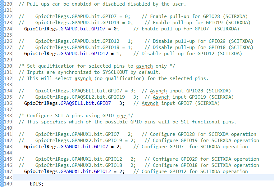
So I connected RX of my module to GPIO12 and TX to GPIO7. In this module, when I send the command "AT" it should return the module name or version. But it doesn't return anything.

It gets stuck in the while loop.

Also I was thinking about the RX/TX level. The module requires a 3.3V logic level and I couldn't find in c2000 datasheet what is the voltage for a HIGH level. So I assume it is 3.3V as well.

Also, I'd like to know how can I write something to the terminal using those ports GPIO7 and 12?? In the echoback example, I noticed that if you transmit something ( scia_msg() ), it will appear in the terminal (just like a printf). Although, if I just change the ports to GPIO7 and 12 (since I will be using those), it won't display anything in the terminal when I transmit something.

ps: I have a code for arduino where I can configure it, and it works just fine.

Any ideas?

Thanks

  • Hi,

    Can you paste the complete code? Delete whatever if required.

    Regards,
    Gautam
  • Hi again, here it is. Nothing ommited.


    // TI File $Revision: /main/4 $
    // Checkin $Date: December 17, 2009   14:36:56 $
    //###########################################################################
    //
    // FILE:    Example_2802xSci_Echoback.c
    //
    // TITLE:   DSP2802x Device SCI Echoback.
    //
    // ASSUMPTIONS:
    //
    //    This program requires the DSP2802x header files.
    //    As supplied, this project is configured for "boot to SARAM" operation.
    //
    //    Connect the SCI-A port to a PC via a transciever and cable.
    //    The PC application 'hypterterminal' can be used to view the data
    //    from the SCI and to send information to the SCI.  Characters recieved
    //    by the SCI port are sent back to the host.
    //
    //    As supplied, this project is configured for "boot to SARAM"
    //    operation.  The 2802x Boot Mode table is shown below.
    //    For information on configuring the boot mode of an eZdsp,
    //    please refer to the documentation included with the eZdsp,
    //
    //    $Boot_Table
    //    While an emulator is connected to your device, the TRSTn pin = 1,
    //    which sets the device into EMU_BOOT boot mode. In this mode, the
    //    peripheral boot modes are as follows:
    //
    //      Boot Mode:   EMU_KEY        EMU_BMODE
    //                   (0xD00)         (0xD01)
    //      ---------------------------------------
    //      Wait         !=0x55AA        X
    //      I/O          0x55AA          0x0000
    //      SCI          0x55AA          0x0001
    //      Wait         0x55AA          0x0002
    //      Get_Mode     0x55AA          0x0003
    //      SPI          0x55AA          0x0004
    //      I2C          0x55AA          0x0005
    //      OTP          0x55AA          0x0006
    //      Wait         0x55AA          0x0007
    //      Wait         0x55AA          0x0008
    //      SARAM        0x55AA          0x000A   <-- "Boot to SARAM"
    //      Flash        0x55AA          0x000B
    //      Wait         0x55AA          Other
    //
    //   Write EMU_KEY to 0xD00 and EMU_BMODE to 0xD01 via the debugger
    //   according to the Boot Mode Table above. Build/Load project,
    //   Reset the device, and Run example
    //
    //   $End_Boot_Table
    //
    //
    //
    // DESCRIPTION:
    //
    //
    //    This test recieves and echo-backs data through the SCI-A port.
    //
    //    1) Configure hyperterminal:
    //       Use the included hyperterminal configuration file SCI_96.ht.
    //       To load this configuration in hyperterminal: file->open
    //       and then select the SCI_96.ht file.
    //    2) Check the COM port.
    //       The configuration file is currently setup for COM1.
    //       If this is not correct, disconnect Call->Disconnect
    //       Open the File-Properties dialog and select the correct COM port.
    //    3) Connect hyperterminal Call->Call
    //       and then start the 2802x SCI echoback program execution.
    //    4) The program will print out a greeting and then ask you to
    //       enter a character which it will echo back to hyperterminal.
    //
    //
    //    Watch Variables:
    //       LoopCount for the number of characters sent
    //       ErrorCount
    //
    //
    //###########################################################################
    // $TI Release: 2802x C/C++ Header Files V1.26 $
    // $Release Date: February 2, 2010 $
    //###########################################################################
    
    #include "DSP28x_Project.h"     // Device Headerfile and Examples Include File
    
    // Prototype statements for functions found within this file.
    void scia_echoback_init(void);
    void scia_fifo_init(void);
    void scia_xmit(int a);
    void scia_msg(char *msg);
    
    // Global counts used in this example
    Uint16 LoopCount;
    Uint16 ErrorCount;
    Uint16 a = 0;
    Uint16 ReceivedChar = 0;
    
    void main(void)
    {
    
    
        char *msg;
    
    // Step 1. Initialize System Control:
    // PLL, WatchDog, enable Peripheral Clocks
    // This example function is found in the DSP2802x_SysCtrl.c file.
       InitSysCtrl();
    
    // Step 2. Initalize GPIO:
    // This example function is found in the DSP2802x_Gpio.c file and
    // illustrates how to set the GPIO to it's default state.
       // InitGpio(); Skipped for this example
    
    // For this example, only init the pins for the SCI-A port.
    // This function is found in the DSP2802x_Sci.c file.
       EALLOW;
    
      /* Enable internal pull-up for the selected pins */
      /* Disable internal pull-up for the selected output pins
         to reduce power consumption. */
      // Pull-ups can be enabled or disabled disabled by the user.
    
      //	GpioCtrlRegs.GPAPUD.bit.GPIO7 = 0;    // Enable pull-up for GPIO28 (SCIRXDA)
      //	GpioCtrlRegs.GPAPUD.bit.GPIO19 = 0;    // Enable pull-up for GPIO19 (SCIRXDA)
      	GpioCtrlRegs.GPAPUD.bit.GPIO7 = 0;     // Enable pull-up for GPIO7  (SCIRXDA)
    
      //	GpioCtrlRegs.GPAPUD.bit.GPIO12 = 1;	   // Disable pull-up for GPIO29 (SCITXDA)
      //	GpioCtrlRegs.GPAPUD.bit.GPIO18 = 1;	   // Disable pull-up for GPIO18 (SCITXDA)
      	GpioCtrlRegs.GPAPUD.bit.GPIO12 = 1;	   // Disable pull-up for GPIO12 (SCITXDA)
    
      /* Set qualification for selected pins to asynch only */
      // Inputs are synchronized to SYSCLKOUT by default.
      // This will select asynch (no qualification) for the selected pins.
    
      //	GpioCtrlRegs.GPAQSEL1.bit.GPIO7 = 3;  // Asynch input GPIO28 (SCIRXDA)
      //	GpioCtrlRegs.GPAQSEL2.bit.GPIO19 = 3;  // Asynch input GPIO19 (SCIRXDA)
      	GpioCtrlRegs.GPAQSEL1.bit.GPIO7 = 3;   // Asynch input GPIO7 (SCIRXDA)
    
      /* Configure SCI-A pins using GPIO regs*/
      // This specifies which of the possible GPIO pins will be SCI functional pins.
    
      //	GpioCtrlRegs.GPAMUX1.bit.GPIO7 = 2;   // Configure GPIO28 for SCIRXDA operation
      //	GpioCtrlRegs.GPAMUX2.bit.GPIO19 = 2;   // Configure GPIO19 for SCIRXDA operation
      	GpioCtrlRegs.GPAMUX1.bit.GPIO7 = 2;    // Configure GPIO7  for SCIRXDA operation
    
      //	GpioCtrlRegs.GPAMUX1.bit.GPIO12 = 2;   // Configure GPIO29 for SCITXDA operation
      //	GpioCtrlRegs.GPAMUX2.bit.GPIO18 = 2;   // Configure GPIO18 for SCITXDA operation
      	GpioCtrlRegs.GPAMUX1.bit.GPIO12 = 2;   // Configure GPIO12 for SCITXDA operation
    
          EDIS;
    
    // Step 3. Clear all interrupts and initialize PIE vector table:
    // Disable CPU interrupts
       DINT;
    
    // Initialize PIE control registers to their default state.
    // The default state is all PIE interrupts disabled and flags
    // are cleared.
    // This function is found in the DSP2802x_PieCtrl.c file.
       InitPieCtrl();
    
    // Disable CPU interrupts and clear all CPU interrupt flags:
       IER = 0x0000;
       IFR = 0x0000;
    
    // Initialize the PIE vector table with pointers to the shell Interrupt
    // Service Routines (ISR).
    // This will populate the entire table, even if the interrupt
    // is not used in this example.  This is useful for debug purposes.
    // The shell ISR routines are found in DSP2802x_DefaultIsr.c.
    // This function is found in DSP2802x_PieVect.c.
       InitPieVectTable();
    
    // Step 4. Initialize all the Device Peripherals:
    // This function is found in DSP2802x_InitPeripherals.c
    // InitPeripherals(); // Not required for this example
    
    // Step 5. User specific code:
    
        LoopCount = 0;
        ErrorCount = 0;
    
        scia_fifo_init();      // Initialize the SCI FIFO
        scia_echoback_init();  // Initalize SCI for echoback
    
        msg = "\r\n\n\nHello World!\0";
        scia_msg(msg);
    
        msg = "\r\nYou will enter a character, and the DSP will echo it back! \n\0";
        scia_msg(msg);
    
        for(;;)
        {
    
           msg = "AT\0"; // Command that asks for info about the bluetooth.
           scia_msg(msg);
    
           // Wait for inc character
           while(SciaRegs.SCIFFRX.bit.RXFFST != 1) { } // wait for XRDY =1 for empty state
    
           // Get character
           ReceivedChar = SciaRegs.SCIRXBUF.all; // I still have to make a function to receive a whole "sentence" instead of only one char
    
           DELAY_US(2000000);
           msg = "AT+NAME\0"; // Command that sets for bluetooth name.
           scia_msg(msg);
           scia_msg("ZUERA\0"); // Set bluetooth name as ZUERA
    
           ReceivedChar = SciaRegs.SCIRXBUF.all; // Bluetooth replies with the name set
    
           DELAY_US(2000000);
    
           // Echo character back
           //msg = "  You sent: \0";
           //scia_msg(msg);
           //scia_xmit(ReceivedChar);
           LoopCount++;
    
        }
    
    }
    
    // Test 1,SCIA  DLB, 8-bit word, baud rate 0x000F, default, 1 STOP bit, no parity
    void scia_echoback_init()
    {
        // Note: Clocks were turned on to the SCIA peripheral
        // in the InitSysCtrl() function
    
        SciaRegs.SCICCR.all =0x0007;   // 1 stop bit,  No loopback
                                       // No parity,8 char bits,
                                       // async mode, idle-line protocol
        SciaRegs.SCICCR.bit.LOOPBKENA = 0;
        SciaRegs.SCICTL1.all =0x0003;  // enable TX, RX, internal SCICLK,
                                       // Disable RX ERR, SLEEP, TXWAKE
        SciaRegs.SCICTL2.all =0x0003;
        SciaRegs.SCICTL2.bit.TXINTENA =1;
        SciaRegs.SCICTL2.bit.RXBKINTENA =1;
    
        // SCI BRR = LSPCLK/(SCI BAUDx8) - 1
        #if (CPU_FRQ_60MHZ)
            SciaRegs.SCIHBAUD    =0x0000;  // 9600 baud @LSPCLK = 15MHz (60 MHz SYSCLK).
            SciaRegs.SCILBAUD    =0x00C2;
        #elif (CPU_FRQ_50MHZ)
            SciaRegs.SCHBAUD     =0x0000;  // 9600 baud @LSPCLK = 12.5 MHz (50 MHz SYSCLK)
        #elif (CPU_FRQ_40MHZ)    =0x00A1;
            SciaRegs.SCIHBAUD    =0x0000;  // 9600 baud @LSPCLK = 10MHz (40 MHz SYSCLK).
            SciaRegs.SCILBAUD    =0x0081;
        #endif
    
        SciaRegs.SCICTL1.all =0x0023;  // Relinquish SCI from Reset
    }
    
    // Transmit a character from the SCI
    void scia_xmit(int a)
    {
        while (SciaRegs.SCIFFTX.bit.TXFFST != 0) {}
        SciaRegs.SCITXBUF=a;
    
    }
    
    void scia_msg(char * msg)
    {
        int i;
        i = 0;
        while(msg[i] != '\0')
        {
            scia_xmit(msg[i]);
            i++;
        }
    }
    
    // Initalize the SCI FIFO
    void scia_fifo_init()
    {
        SciaRegs.SCIFFTX.all=0xE040;
        SciaRegs.SCIFFRX.all=0x2044;
        SciaRegs.SCIFFCT.all=0x0;
    
    }
    
    //===========================================================================
    // No more.
    //===========================================================================
    

  • Hey Gautam,

    Do you see anything wrong in my code?

    Thanks

  • Hi,

    Sorry that I missed your updated post. GPIO config seems fine but on the hardware side, is your bluetooth module interfaced with TTL or RS-232 logic?

    Also, nothing will get displayed on the PC as these GPIOs need to be converted to proper level.


    Regards,
    Gautam

  • Unfortunately the bluetooth module (HC-06) has a very poor datasheet. The only information I could find was in its name: It's called "HC-06 RS232 TTL module". So I cannot say for sure. I am still trying to find out for sure, but I'd say it is RS232.

    Although, with the code above, I noticed that *sometimes* it partially works. By that I mean I can sometimes set the bluetooth name and it would actually change. And when it changes, it misses some characters or get them wrong.
    For example, when I changed the name of it to "Testing this", and checked it on my android, the bluetooth network available was: "Te◘¶ing thᶲ◘"

    Could this be a baudrate problem??

    The bluetooth device is at a 9600 BR (default) and in the code the if statement in (CPU_FRQ_60MHZ) sets the communication to that BR too. If it is a BR problem then maybe the bluetooth device isn't at 9600 (even though it comes as default).

  • Yes, baud rate can be an issue but I've worked on this module and its sibling HC-05 and both respond really well. HC-05 module that I'd was a 5V logic based board and HC-06 was a 3.3V based. Hence you need to be clear that the module you've has an add-on board with 3.3V/5V friendly connections.

    Here was the module-on-board pin-out that I'd:


    If 3.3V then you can directly connect TX and RX to your controller and don't forget to connect both the grounds too.


    Regards,

    Gautam

  • Thanks a lot for the help Gautam, but I've found the problem: HC-06 was faulty.

    I replaced it with another one (exactly the same model my friend happened to have) and it worked just fine.

    Thanks again :)

  • Excellent!

    Goodluck & Regards,
    Gautam