- Ask a related questionWhat is a related question?A related question is a question created from another question. When the related question is created, it will be automatically linked to the original question.


Hi,
My configuration Hardware:
- TMS320F28335 Experimenter Kit
I have a problem with the McBSP used as SPI operation as Master.
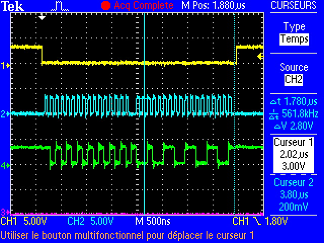
When i send 2 words (more than 1 word), the first word has the good number of clock (16 clocks for 16 bits) but the second word has 18 clocks for only 16 valid bits as seen on figure below.
My configuration software:
/* Step 1 : Place the transmitter and receiver inreset */
OMCB_McbspaRegs.SPCR2.bit.XRST = 0; /* Transmitter reset */
OMCB_McbspaRegs.SPCR1.bit.RRST = 0; /* Receiver reset */
/* Step 2 : Place the sample rate generator in reset */
OMCB_McbspaRegs.SPCR2.bit.GRST = 0; /* Sample Rate generator Reset */
OMCB_McbspaRegs.SPCR2.bit.FRST = 0; /* Frame Sync generator reset */
/* Step 3 : Program registers that affect SPI operation */
/* Serial Port Control 1 Register */
OMCB_McbspaRegs.SPCR1.bit.DLB = 0; /* For Test only */
OMCB_McbspaRegs.SPCR1.bit.CLKSTP = 2; /* Low active state without delay, with CLKXP = 0 and CLKRP = 0 */
/* The McBSP transmits data on the rising edge of CLKG */
/* and receives data on the falling edge of CLKG */
/* Serial Port Control 2 Register */
/* Receive Control Register 1 */
OMCB_McbspaRegs.RCR1.bit.RWDLEN1 = 2; /* 16-bits word (receiver) */
OMCB_McbspaRegs.RCR1.bit.RFRLEN1 = 0; /* 1 word length (receiver) */
/* Receive Control Register 2 */
OMCB_McbspaRegs.RCR2.bit.RDATDLY = 1; /* This setting provides the correct setup time on the FSX Signal */
OMCB_McbspaRegs.RCR2.bit.RWDLEN2 = 2; /* 16-bits word */
OMCB_McbspaRegs.RCR2.bit.RFIG = 0; /* Frame synchronisation detect */
/* Transmit Control Registers 1 */
OMCB_McbspaRegs.XCR1.bit.XWDLEN1 = 2; /* 16-bits word (transmitter) */
OMCB_McbspaRegs.XCR1.bit.XFRLEN1 = 0; /* 1 words length (transmitter) */
/* Transmit Control Registers 2 */
OMCB_McbspaRegs.XCR2.bit.XWDLEN2 = 2; /* 16-bits word */
OMCB_McbspaRegs.XCR2.bit.XDATDLY = 1; /* This setting provides the correct setup time on the FSX Signal */
OMCB_McbspaRegs.XCR2.bit.XFIG = 0; /* Frame synchronisation detect */
/* Sample Rate Generator 1 Register */
OMCB_McbspaRegs.SRGR1.bit.CLKGDV = 3; /* clock = Input clock / (CLKGDV+1) => clk=> 37.5/4 = 9.375Mhz */
OMCB_McbspaRegs.SRGR1.bit.FWID = 0; /* Frame Width = 0 => 1 Pulse */
/* Sample Rate Generator 2 Register */
OMCB_McbspaRegs.SRGR2.bit.CLKSM = 1; /* CLKSM = 1 and SCLKME= 0 => Input clock (LSPCLK) */
/* Pin Control Register */
OMCB_McbspaRegs.PCR.bit.FSXM = 1; /* Transmit frame synchronization is generated internally by the Sample Rate generator */
OMCB_McbspaRegs.PCR.bit.FSRM = 1; /* Receive frame synchronization is supplied by the sample rate generator */
OMCB_McbspaRegs.PCR.bit.CLKXM = 1; /* In clock stop mode => The McBSP is a master in the SPI Protocol */
OMCB_McbspaRegs.PCR.bit.CLKRM = 1; /* digital loopback disable => */
/* Internal MCLKR is driven by the sample rate generator of the McBSP */
OMCB_McbspaRegs.PCR.bit.SCLKME = 0; /* CLKSM = 1 and SCLKME= 0 => Input clock (LSPCLK) */
OMCB_McbspaRegs.PCR.bit.FSXP = 1; /* Transmit frame-synchronization pulses are active low */
OMCB_McbspaRegs.PCR.bit.CLKRP = 0; /* The McBSP receives data on the falling edge of CLKG */
OMCB_McbspaRegs.PCR.bit.CLKXP = 0; /* The McBSP transmits data on the rising edge of CLKG */
/* McBSP Interrupt Enable Register */
OMCB_McbspaRegs.MFFINT.bit.XINT = 1; /* Enable Transmit Interrupts */
OMCB_McbspaRegs.MFFINT.bit.RINT = 1; /* Enable Receive Interrupts */
/* Step 4 : Enable the sample rate generator */
OMCB_McbspaRegs.SPCR2.bit.GRST = 1; /* Enable the sample rate generator */
for(cpt = 0; cpt < 200; cpt++); /* Wait at least 2 SRG clock cycles */
/* Step 5 : Enable the transmitter and receiver */
OMCB_McbspaRegs.SPCR2.bit.XRST=1;
OMCB_McbspaRegs.SPCR1.bit.RRST=1;
/* Step 6 : Enable the Frame synchronization logic of the sample rate generator */
OMCB_McbspaRegs.SPCR2.bit.FRST=1;
I use interrupt for Tx and Rx.
When the McBSP work on Loopback, they read the correct value.
But when i want communicate with other device, the 'useless' clocks cause a bad reading word.


Thanks for helping