This thread has been locked.
If you have a related question, please click the "Ask a related question" button in the top right corner. The newly created question will be automatically linked to this question.
Hi everyone,
I'm trying to modify the code PHY_G3_EXAMPLE to acquire some data as SNR, Reception Quality etc.
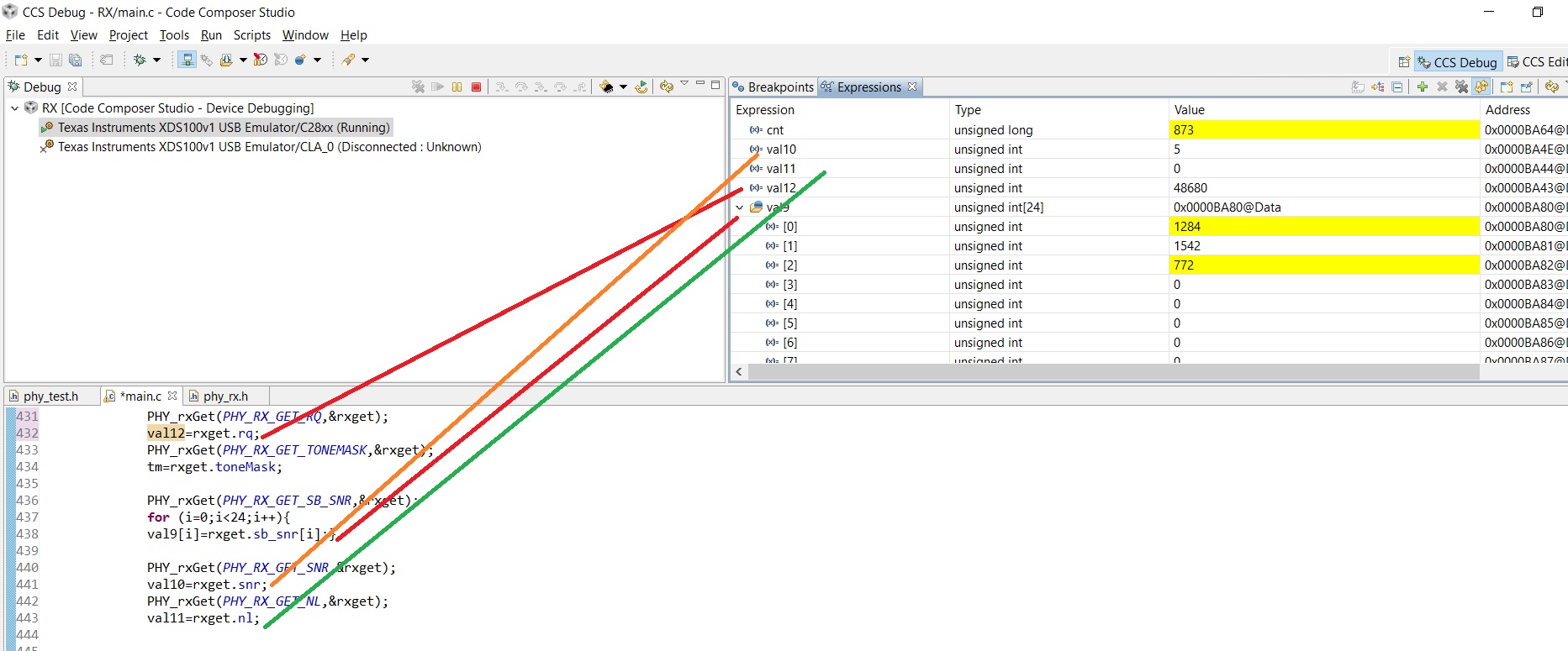
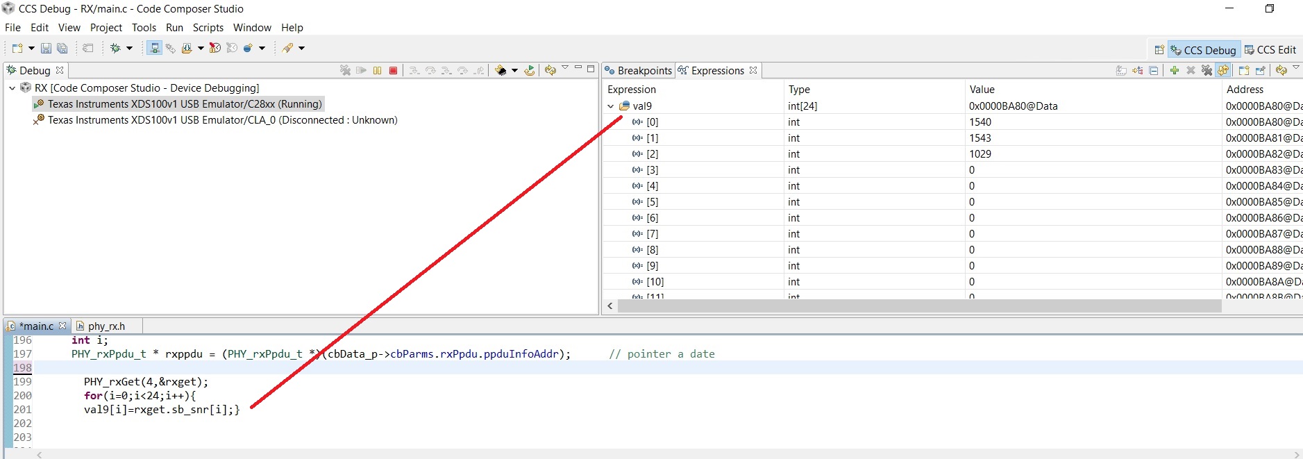
I have some trouble to understand how does the PHY_rxGet(UINT16 getType, UINT16 *getData_p) works. I have implemented this function inside the code by first declaring the structure -> PHY_rxGetData_t rxget and then recall the PHY_rxGet function for example in this way:
-PHY_rxGet(PHY_RX_GET_TONEMAP_INFO,&rxget);
val10=rxget.toneMapInfo;
-PHY_rxGet(PHY_RX_GET_NL,&rxget);
val7=rxget.nl; etc...
The problem is that when I look the variables: val10, val7 (that I have declared before as UIN16) the result is 0. Only If I put inside the function "PHY_RX_GET_TONEMASK" correspond with the TX value, but for example if I want to know the SNR (so I put inside the function "PHY_RX_GET_SNR" ) or other parameter (as NoiseLevel, sb_SNR, ReceptionQuality..) the value is always 0.
Can someone tell me the reason?
Thanks for your support,
Best,
Andrea
Hi Katta,
Thanks for replying.
I call PHY_rxGet(..) in the main.c, precisely in that part of the code:
void cb_ppdu(PHY_ev_t eventID, PHY_cbData_t *cbData_p)
{
if (cbData_p->status == PHY_STAT_SUCCESS)
{............}
That mean, each time a packet arrives and a GPIO LED blink.
I tried also to create a function:
void getvalue(void) {
PHY_rxGetData_t rxget;
PHY_rxGet(PHY_RX_GET_RQ,&rxget);
val12=rxget.rq;
PHY_rxGet(PHY_RX_GET_SNR,&rxget);
val10=rxget.snr;
PHY_rxGet(PHY_RX_GET_NL,&rxget);
val11=rxget.nl;
.......... }
that is called every 1second from PRD DSP BIOS but the problem is that the NOISE LEVEL, RECEPTION QUALITY, SNR, SINGLE_SBN_SNR are always zero, others values in PHY_rxGet(..) (as TONE_MASK) are right and different from zero.
I hope for your support.
Best,
Andrea
Hi Katta,
I'm not using the "Zero Configuration GUI" but my own program based on the G3_PHY_EXAMPLE.
Everything works well: the TX TMDPLCKIT-V3 send a packet every 1second and the RX TMDPLCKIT-V3 receive that packet and blink a LED.
I'd like to acquire the parameters: SNR, SBN_SNR, NL, RQ and I thought that was enough to call the function in my RX_code.
The other statistics, as I mentioned before, works. For example, using phyRxPpduCount, I see that the value increase.
If you want, I can send my modified code so you can take a look.
Thanks a lot in advance,
Andrea
Hi Katta,
1) Yes, the system is running. However I tried to stop the system with a breakpoint but the values are the same.
From a certain point of view, val10 that is my SNR is correct (because it has to reach values from 0 to 7) , I have 5.
But the other values for example val12, that is my ReceptionQuality has the value 48680 that is wrong because on phy_rx.h is write:
UINT16 rq; // receive quality (0 to 8 from bad to good)"
2) I tried also to save the values in a buffer but the results are more or less the same.
My guess it that is like is missing some convertion or format number for the other parameters.
I hope again for your support,
Andrea
I attach here my RX main.c so you can take a look.
The program, in a few word, blink the LED everytime a packet in sent from the TX TMDSPLCKIT-V3.
I hope it can help you to understand better,
Best,
Andrea
/****************************************************************************** * FILE PURPOSE: This file implements the G3 PHY TX/RX Test ******************************************************************************* * * FILE NAME: test_tx_rx.c * * ******************************************************************************/ /* configuration file */ #ifdef F2806X #include <test_tx_rx_f2806xcfg.h> #elif defined (F28M35X) #include <test_tx_rx_f28m35xcfg.h> #else #include <test_tx_rxcfg.h> #endif #include "DSP28x_Project.h" #include <phy_rx.h> #include <phy_tx.h> #include <phy_test.h> #include <hal_afe.h> #include <phy_tx_swi.h> #define VETTORE_LENG 1 #define PHY_RX_BUF_SIZE 10 int16 line_buffer[VETTORE_LENG]; int16 rx_ppduBuf[PHY_RX_BUF_SIZE]; UINT16 getCRC8(uint16 input_crc8_accum, uint16 *msg, parity_t parity, uint16 rxLen); UINT16 getCRC8_vcu_asm(uint32 input_crc8_accum, uint16 *msg, parity_t parity, uint16 rxLen); //VARIABLES UINT16 val1,val2,val3,val4,val5,val6,val7,val8,*valp1,val9[24], val10,val11,val12,val13,val14,snr,quality; UINT32 cnt; PHY_rxAagcGet_t agc; PHY_rxCdGet_t cd; PHY_rxToneMask_t tm; void ledBlink_gpio31(); void Setup_eCAP1(void); void eCAP1_isr(void); PHY_txSetData_t test_toneMask_s = { 0x2417,//2417 18- 24 sub carriers 01- start tone 1*1,5625 kHz = 1,5625 kHz 0xFFFF,//FFFF 0xFFFF,//FFFF 0x000F,//000F 0x0000,//0000 0x0000,//0000 0x0000//0000 }; //Receiver Gain PHY_rxAagcSet_t agc_gain_s = { 0,//0-auto 1-manual //7//0-7 step 6dB }; void flash_setup(void); void sys_init_phy_rx(void); void sys_init_phy_tx(void); void PHY_tx_sema_post(); void get_tutto(); extern void cb_bit(PHY_ev_t eventID, PHY_cbData_t *cbData_p); void cb_ppdu(PHY_ev_t eventID, PHY_cbData_t *cbData_p); UINT32 idle_cnt=0; #ifdef P1901_2_FCC UINT32 test_toneMap = 0xFFFFFF; #else UINT32 test_toneMap = 0x003F;//3F 1bit presents 6 tones (sub carriers) #endif UINT16 test_toneCoef[2] = {0x0000, 0x0000};//each 4-bit field is 2-compliment gain /****************************************************************************** * FUNCTION NAME: sys_init * * DESCRIPTION: ******************************************************************************/ void sys_init_hw(void) { // Step 1. Initialize System Control: // PLL, WatchDog, enable Peripheral Clocks // This example function is found in the DSP2833x_SysCtrl.c file. DINT; // Global Disable all Interrupts IER = 0x0000; // Disable CPU interrupts IFR = 0x0000; // Clear all CPU interrupt flags // Step 1. Initialize System Control: // PLL, WatchDog, enable Peripheral Clocks // This example function is found in the DSP2833x_SysCtrl.c file. InitSysCtrl(); Setup_eCAP1(); // init eCAP1 /* Map ePWM registers to PF3 */ EALLOW; // SysCtrlRegs.MAPCNF.bit.MAPEPWM = 1; EDIS; // Step 1a. Reset peripherals DMAInitialize(); // RLiang TX-PHY need this one InitCpuTimers(); // Specific clock setting for this example: //EALLOW; //SysCtrlRegs.HISPCP.all = ADC_MODCLK; // HSPCLK = SYSCLKOUT/ADC_MODCLK //EDIS; // Step 2. Initialize GPIO: // This example function is found in the DSP2833x_Gpio.c file and // illustrates how to set the GPIO to it's default state. // InitGpio(); // Skipped for this example // Step 3. Clear all interrupts and initialize PIE vector table: // Disable CPU interrupts DINT; // Initialize the PIE control registers to their default state. // The default state is all PIE interrupts disabled and flags // are cleared. // This function is found in the DSP2833x_PieCtrl.c file. InitPieCtrl(); // Disable CPU interrupts and clear all CPU interrupt flags: IER = 0x0000; IFR = 0x0000; // Initialize the PIE vector table with pointers to the shell Interrupt // Service Routines (ISR). // This will populate the entire table, even if the interrupt // is not used in this example. This is useful for debug purposes. // The shell ISR routines are found in DSP2833x_DefaultIsr.c. // This function is found in DSP2833x_PieVect.c. InitPieVectTable(); PieCtrlRegs.PIEIER4.bit.INTx1 = 1; // Enable ECAP1_INT in PIE group 4 IER |= 0x0009; // Enable INT4 and INT1 // Enable global Interrupts and higher priority real-time debug events: EINT; // Enable Global interrupt INTM ERTM; // Enable Global realtime interrupt DBGM } /***********************************************************************/ /* Call back for PHY_rxPpdu BitDone */ /***********************************************************************/ void cb_ppdu(PHY_ev_t eventID, PHY_cbData_t *cbData_p) { if (cbData_p->status == PHY_STAT_SUCCESS) { int i; PHY_rxPpdu_t * rxppdu = (PHY_rxPpdu_t *)(cbData_p->cbParms.rxPpdu.ppduInfoAddr); // pointer a date int *data = (int *)rxppdu->data_p; PHY_rxPpduRelease(rxppdu); //BLINK LED EVERYTIME PACKET ARRIVES// GpioDataRegs.GPATOGGLE.bit.GPIO31 = 1; } } /****************************************************************************** * FUNCTION NAME: main ******************************************************************************/ void main(Void) { HAL_afe_prfParms_t afePrfParms; PHY_rxPpdu_t PHY_rx_ppdu_s; /* initialize HW */ sys_init_hw(); /* setup for flash */ flash_setup(); /* init LED */ //LED_init(); EALLOW; GpioCtrlRegs.GPBMUX1.bit.GPIO34 = 0; //0-GPIO GpioCtrlRegs.GPBDIR.bit.GPIO34 = 1; //1-output GpioCtrlRegs.GPAMUX2.bit.GPIO31 = 0; //0-GPIO GpioCtrlRegs.GPADIR.bit.GPIO31 = 1; //1-output GpioCtrlRegs.GPAMUX1.bit.GPIO6 = 0; //0-GPIO GpioCtrlRegs.GPADIR.bit.GPIO6 = 1; //1-output GpioCtrlRegs.GPAMUX1.bit.GPIO7 = 0; //0-GPIO GpioCtrlRegs.GPADIR.bit.GPIO7 = 1; //1-output GpioCtrlRegs.GPAMUX1.bit.GPIO8 = 0; //0-GPIO GpioCtrlRegs.GPADIR.bit.GPIO8 = 1; //1-output /* HAL profile (tx/rx sampling and PWM frequencies */ #ifdef AFE031 /* AFE031 requires 3x TX sampling rate */ afePrfParms.tx_fs_kHz = HAL_AFE_KHZ_1200;//1200 #else afePrfParms.rx_fs_kHz = HAL_AFE_KHZ_400;//400 afePrfParms.tx_fs_kHz = HAL_AFE_KHZ_400;//400 afePrfParms.tx_pwm_kHz = HAL_AFE_KHZ_1200;//1200 #endif #if defined(CENELEC_B) || defined(CENELEC_BC) afePrfParms.band = 1; #else afePrfParms.band = 0; #endif HAL_afeInit(&afePrfParms); /* init PHY Rx */ sys_init_phy_rx(); /* init PHY TX */ sys_init_phy_tx(); /* Set tonemask */ PHY_rxSet(PHY_RX_SET_TONEMASK, (PHY_rxSetData_t *)&test_toneMask_s); PHY_rxSet(PHY_RX_SET_AGC, (PHY_rxSetData_t *)&agc_gain_s); // initialize PHY band and reconfigure the afe parameters PHY_init(); PHY_rx_ppdu_s.data_p = (Uint16 *)&rx_ppduBuf[0]; /* Start PHY Rx */ PHY_rxStart(0xFFFF, cb_ppdu); /* Register for bit start */ PHY_rxBitStartIndicate(cb_bit); /* enable sys interrupt */ EnableInterrupts(); } Uint32 blinkCnt=0; void ledBlink_gpio31() { #ifdef F28M35X // silicon errata: sprz357.pdf if(GpioG1DataRegs.GPCDAT.bit.GPIO71 == 0){ GpioG1DataRegs.GPCSET.bit.GPIO71 = 1; }else{ GpioG1DataRegs.GPCCLEAR.bit.GPIO71 = 1; } #else GpioDataRegs.GPBTOGGLE.bit.GPIO34 = 1; #endif blinkCnt++; } void get_all(void){ int i; /*I can call this function from DSP BIOS PRD EVERY SECOND (for example) Or put All this stuff inside the callback when BLINK THE LED * BUT THE RESULTS IS THE SAME, SNR WORK BUT OTHER VARIABLES NOT */ //STATISTICS PHY_rx_stat_t rxstats; PHY_rxGetStat(&rxstats); val1=rxstats.phyAgcStepNum; val2=rxstats.phyAgcStepValue; val3=rxstats.phyCrcFailCount; val4=rxstats.phyRxDropCount; val5=rxstats.phyRxQueueLen; val6=rxstats.phyCrcIncorrectCount; cnt=rxstats.phyRxPpduCount; //.... PHY_rxGetData_t rxget; PHY_rxGet(4,&rxget); //I PUT HERE "4" BUT IS THE SAME IF I COPY THE PHY_RX_RQ ON PHY_RX.H" val12=rxget.rq; PHY_rxGet(PHY_RX_GET_TONEMASK,&rxget); tm=rxget.toneMask; PHY_rxGet(PHY_RX_GET_SNR,&rxget); val10=rxget.snr; PHY_rxGet(PHY_RX_GET_NL,&rxget); val11=rxget.nl; } // CRC8 convertion function uint16 getCRC8 (uint16 input_crc8_accum, uint16 * msg, parity_t parity, uint16 rxLen) { return getCRC8_vcu_asm(input_crc8_accum, msg, parity, rxLen); }