


Hi Ti Team,
As i know that when using digital control system we use to work in Z plane. And using tustin transform an can convert the s plane transfer function to z-plane transfer function.
As we know using bode plot we can find the frequency response of an LTI system. And frequency responce is found for s with σ = 0 :--
s = σ + j ω
= 0 + j ω
= j ω
In bode plot to be stable system we have to remain away from 1 & -180 degree (I will not discuss about sensivity at present).
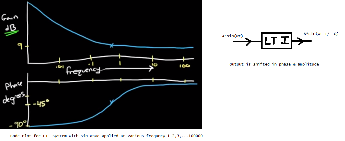
I have pasted a image below where i am subjecting LTI to an A*sin(wt) & o/p signal is B*sin(wt +/- Q). And I am testing this for large range of frequency & obtained the bode plot of my LTI system. Form Bode plot we can get the Gain & phase margin of the system.
But now what exactly this phase & gain margin means when we use software & MCU.
1> Does gain margin means how much delay is acceptable in my software or parasitic delay of MOTOR, after sensing the rotor position & running control algorithm &Then applying waveform to actual motor ?
Means to say by phase delay does it means software delay(of control algorithm) acceptable after sensing rotor position & final PWM applied to inverter MOSFET of motor ?
But unit for delay in software is msec or usec but unit of phase margin & gain margin is in degree & DB. How to interrelate unit degree with second ?
2> Also what exactly we mean by Gain margin & phase margin when we develop digital control system with software & MCU ?
Please suggest
Regards,
Dinesh

