This thread has been locked.

If you have a related question, please click the "Ask a related question" button in the top right corner. The newly created question will be automatically linked to this question.

TMS320F28335: ADC DOES NOT READ VALUE

Part Number: TMS320F28335
Other Parts Discussed in Thread: CONTROLSUITE, REF3120, OPA320, OPA350

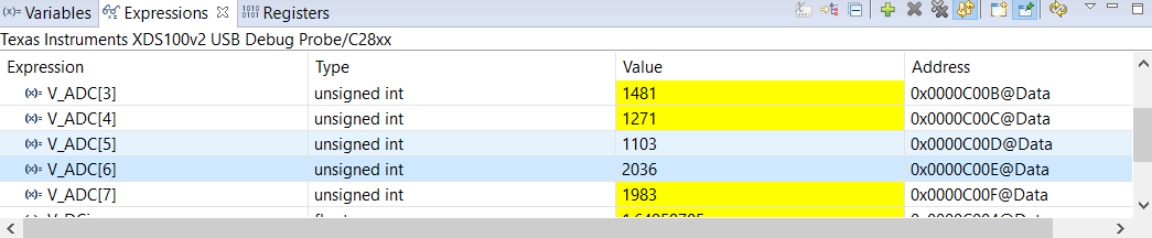
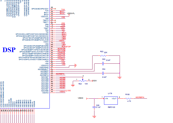
F28335 ADC dont work. I check the pins. I change input voltage then change voltage value to adc pin but adcresult register values does not change also adcresult6 adcresult7 register values changes always even input gnd other adcresult register constant value but when i change input voltage adcresultregister dont effect anything. What can be the source of these adcresult6-7 changes.

  • Hakan,

    There are several possibilities why you might not be getting the right readings from the ADC. The best way to proceed is to open one of the F28335 example projects in controlSUITE and check that it works. There is an example entitled "adc_soc" which continuously reads two channels into a pair of arrays. I recommend trying that. If you get expected results you have something wrong in your code, otherwise it's likely to be a hardware problem.

    Regards,

    Richard
  • I triying run adc_soc example but nothing change adc does not read any value. I also check adcresext, adcrefp, adcrefm , adcrefin ,adcclo pins. The element and voltage values connected to these pins are correct.For example i change  dc voltage ,the voltage coming to the ADCIN6 pin is  1.356 V but AdcRegs.ADCRESULT6 value change continuously. I use my dsp control card other functons for example pwm, gpio correctly but adc have problem.

  • Hakan,

    What hardware are you using - is it a TI development kit, or your own board?

    Also, can you send me just your ADC initialization code please?  Thanks.

    Regards,

    Richard

  • Hi Ricard,

    I use my own board i send photo you my board schematic of part of adc . There is strange event. When i use adc pins  adcin0-5 adcresult value constant but dont read anything random value but when i use pin adcin6 and adcin7 As I pictured before adcresult value changing alwalys. Also i triying to change different chanels  to adcin pin but nothing change.After all I can not use adc in any case. Last thing I use XCLKIN 30MHz . Could it be a problem from this?

    thank your help

    I hope we can find a solution to this problem

    Best regards,

    Hakan

    #include "DSP28x_Project.h"    

    __interrupt void adc_isr(void);

    Uint16 LoopCount;

    Uint16 ConversionCount;

    Uint16 Voltage1[10];

    Uint16 Voltage2[10];

    main()

    {

      InitSysCtrl();

      EALLOW;

      #if (CPU_FRQ_150MHZ)     // Default - 150 MHz SYSCLKOUT

        #define ADC_MODCLK 0x3 // HSPCLK = SYSCLKOUT/2*ADC_MODCLK2 = 150/(2*3)   = 25.0 MHz

      #endif

      #if (CPU_FRQ_100MHZ)

        #define ADC_MODCLK 0x2 // HSPCLK = SYSCLKOUT/2*ADC_MODCLK2 = 100/(2*2)   = 25.0 MHz

      #endif

      EDIS;

      EALLOW;

      SysCtrlRegs.HISPCP.all = ADC_MODCLK;

      EDIS;

      DINT;

      InitPieCtrl();

      IER = 0x0000;

      IFR = 0x0000;

      InitPieVectTable();

      EALLOW;  // This is needed to write to EALLOW protected register

      PieVectTable.ADCINT = &adc_isr;

      EDIS;    // This is needed to disable write to EALLOW protected registers

      InitAdc();  // For this example, init the ADC

    // Enable ADCINT in PIE

      PieCtrlRegs.PIEIER1.bit.INTx6 = 1;

      IER |= M_INT1; // Enable CPU Interrupt 1

      EINT;          // Enable Global interrupt INTM

      ERTM;          // Enable Global realtime interrupt DBGM

      LoopCount = 0;

      ConversionCount = 0;

    // Configure ADC

      AdcRegs.ADCMAXCONV.all = 0x0003;       // Setup 2 conv's on SEQ1

      AdcRegs.ADCCHSELSEQ1.bit.CONV00 = 0x6; // Setup ADCINA3 as 1st SEQ1 conv.

      AdcRegs.ADCCHSELSEQ1.bit.CONV01 = 0x7; // Setup ADCINA2 as 2nd SEQ1 conv.

      AdcRegs.ADCTRL2.bit.EPWM_SOCA_SEQ1 = 1;// Enable SOCA from ePWM to start SEQ1

      AdcRegs.ADCTRL2.bit.INT_ENA_SEQ1 = 1;  // Enable SEQ1 interrupt (every EOS)

    // Assumes ePWM1 clock is already enabled in InitSysCtrl();

      EPwm1Regs.ETSEL.bit.SOCAEN = 1;        // Enable SOC on A group

      EPwm1Regs.ETSEL.bit.SOCASEL = 4;       // Select SOC from from CPMA on upcount

      EPwm1Regs.ETPS.bit.SOCAPRD = 1;        // Generate pulse on 1st event

      EPwm1Regs.CMPA.half.CMPA = 0x0080;  // Set compare A value

      EPwm1Regs.TBPRD = 0xFFFF;              // Set period for ePWM1

      EPwm1Regs.TBCTL.bit.CTRMODE = 0;  // count up and start

    // Wait for ADC interrupt

      for(;;)

      {

         LoopCount++;

      }

    }

    __interrupt void  adc_isr(void)

    {

     Voltage1[ConversionCount] = AdcRegs.ADCRESULT0 >>4;

     Voltage2[ConversionCount] = AdcRegs.ADCRESULT1 >>4;

     // If 40 conversions have been logged, start over

     if(ConversionCount == 9)

     {

        ConversionCount = 0;

     }

     else

     {

         ConversionCount++;

     }

     // Reinitialize for next ADC sequence

     AdcRegs.ADCTRL2.bit.RST_SEQ1 = 1;         // Reset SEQ1

     AdcRegs.ADCST.bit.INT_SEQ1_CLR = 1;       // Clear INT SEQ1 bit

     PieCtrlRegs.PIEACK.all = PIEACK_GROUP1;   // Acknowledge interrupt to PIE

     return;

    }

  • Hakan,

    Where are you setting the ADCREFSEL register to use the external reference - is it done in AdcInit()?

    Also, the schematic doesn't show a ground connection to the REF3120. Is there one?

    Regards,

    Richard
  • Richard,
    You are right ı forgot to change ADCREFSEL.Now i added AdcRegs.ADCREFSEL.bit.REF_SEL =0x1; in InitAdc(); and I checked that it changed from 0x1F27 to 0x5F27 but the problem continues. And REF3120 has ground connection on third pin.

    Best Regards,
    Hakan
  • Hakan,

    The fact you get a changed reading implies this is a configuration issue rather than a hardware one. Can you look carefully at the ADC clocking to be sure you are not exceeding 25 MHz at the peripheral? The attached diagram shows which registers and fields you need to look at.

    Set a break-point in the code after everything is initialized and check the registers contents in CCS.

    Regards,

    Richard
  • Hi Ricard,
    First of all thanks for your help, Now adc works when i change voltage diffrence in adcresults logical but adc still have problems. The problem is for example a fixed voltage(1.47V) adc reads like 2002, 2018, 2030, 2040 values. There is almost 40 value error when i change voltage it reads another value but new values hve difference each other again 40 values for example 1800, 1820,1810, 1842. Where does this problem originate ? I observe to voltage to input adc oscilloscope seems constant.If the voltage is constant, the value read by the ADC does not have to be the same?

    Best Regards,
    Hakan
  • Hi Hakan,

    The fluctuations equate to something like 30mV of noise at the ADC input. How much noise are you measuring there? If it's significantly less than that you may want to try increasing the acquisition window length (ACQ_PS field in ADCTRL1 register).

    Regards,

    Richard
  • Hi Hakan,

    Do you have a buffer after the 4.7k ohm resistor driving the ADC reference voltage?  ADC references need a very low impedance and high bandwidth driver.  

    You might try replacing this with 0-ohm and also adding as large of a capacitor to VSSA as the REF3120 output can drive...maybe 2.2uF would be a good place to start.  If this isn't adequate, you should try buffering with an op-amp.  We recommend OPA320 or OPA350 for some of our newer devices, but these should work here too.  

  • Hi Richard and Devin
    I tried I tried changing ADC_MODCLK and ACQ_PS. I increased both but still the same problem continues. I have no buffer after 4.7k ohm resistor. There is a 4.7k resistor at the output of the ref3120 and this is connected to the adcrefin. I can not add a buffer to the dsp board for the moment because card already made. But i have a question. Will the result change if a lower valued resistor is added instead of 4.7k resistor to solve the problem for now? or Adcrefin directly to the ground.
    Thanks for help
    Best Regards
    Hakan
  • Hi Hakan,

    I think you will definitely want to replace the 4.7k resistor with a 0-ohm shunt.  You would also want to add a capacitor that is at least ~1uF between the VREF input and ground.  

    Increasing ACQ_PS can help with settling time on ADC inputs in case of high impedance driver, but it won't help if the ADC reference is not good.