
- Ask a related questionWhat is a related question?A related question is a question created from another question. When the related question is created, it will be automatically linked to the original question.

Hi all,
I m working with f28379d connected to a PCAN usb. what im trying to do is create a program that sends messages from CAN A to PCAN and also receives Messages from PCAN to CAN A. The transmitting of the messages works fine partially, the message id is not displayed on PCAN, where as trasmitted data displayed properly on PCAN. Looks like some register configuration missed, is it because of the reason mentioned in Please confirm.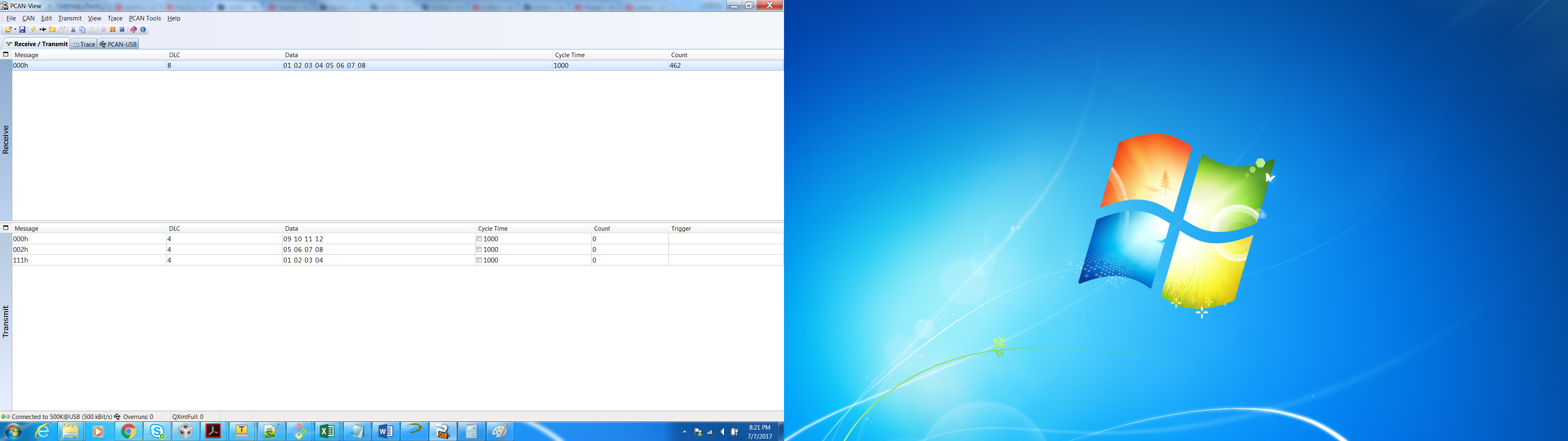
The source code is as follows and pcan screen shot attached with this post. Cofigured the pin mux as per my setup, CANA used for both TX and RX.
//###########################################################################
//
// FILE: can_loopback_bitfields.c
//
// TITLE: Example to demonstrate basic CAN setup and use.
//
//! \addtogroup cpu01_example_list
//! <h1>CAN External Loopback Using Bitfields (can_loopback_bitfields)</h1>
//!
//! IMPORTANT: CAN Bitfield headers require compiler v16.6.0.STS and newer!
//!
//! This example, using bitfield headers, shows the basic setup of CAN in
//! order to transmit and receive messages on the CAN bus. The CAN
//! peripheral is configured to transmit messages with a specific CAN ID.
//! A message is then transmitted once per second, using a simple delay
//! loop for timing. The message that is sent is a 4 byte message that
//! contains an incrementing pattern.
//!
//! This example sets up the CAN controller in External Loopback test mode.
//! Data transmitted is visible on the CAN0TX pin and can be received with
//! an appropriate mailbox configuration.
//!
//
//###########################################################################
// $TI Release: F2837xD Support Library v3.01.00.00 $
// $Release Date: Mon May 22 15:43:40 CDT 2017 $
// $Copyright:
// Copyright (C) 2013-2017 Texas Instruments Incorporated - http://www.ti.com/
//
// Redistribution and use in source and binary forms, with or without
// modification, are permitted provided that the following conditions
// are met:
//
// Redistributions of source code must retain the above copyright
// notice, this list of conditions and the following disclaimer.
//
// Redistributions in binary form must reproduce the above copyright
// notice, this list of conditions and the following disclaimer in the
// documentation and/or other materials provided with the
// distribution.
//
// Neither the name of Texas Instruments Incorporated nor the names of
// its contributors may be used to endorse or promote products derived
// from this software without specific prior written permission.
//
// THIS SOFTWARE IS PROVIDED BY THE COPYRIGHT HOLDERS AND CONTRIBUTORS
// "AS IS" AND ANY EXPRESS OR IMPLIED WARRANTIES, INCLUDING, BUT NOT
// LIMITED TO, THE IMPLIED WARRANTIES OF MERCHANTABILITY AND FITNESS FOR
// A PARTICULAR PURPOSE ARE DISCLAIMED. IN NO EVENT SHALL THE COPYRIGHT
// OWNER OR CONTRIBUTORS BE LIABLE FOR ANY DIRECT, INDIRECT, INCIDENTAL,
// SPECIAL, EXEMPLARY, OR CONSEQUENTIAL DAMAGES (INCLUDING, BUT NOT
// LIMITED TO, PROCUREMENT OF SUBSTITUTE GOODS OR SERVICES; LOSS OF USE,
// DATA, OR PROFITS; OR BUSINESS INTERRUPTION) HOWEVER CAUSED AND ON ANY
// THEORY OF LIABILITY, WHETHER IN CONTRACT, STRICT LIABILITY, OR TORT
// (INCLUDING NEGLIGENCE OR OTHERWISE) ARISING IN ANY WAY OUT OF THE USE
// OF THIS SOFTWARE, EVEN IF ADVISED OF THE POSSIBILITY OF SUCH DAMAGE.
// $
//###########################################################################
//
// Included Files
//
#include "F28x_Project.h"
//
// Defines
//
//#define CAN_MSG_ID 0x1111
#define CAN_MSG_ID 0x0580
#define CAN_TX_MSG_OBJ 1
#define CAN_RX_MSG_OBJ 2
#define CAN_MAX_BIT_DIVISOR (13) // The maximum CAN bit timing divisor
#define CAN_MIN_BIT_DIVISOR (5) // The minimum CAN bit timing divisor
#define CAN_MAX_PRE_DIVISOR (1024) // The maximum CAN pre-divisor
#define CAN_MIN_PRE_DIVISOR (1) // The minimum CAN pre-divisor
#define CAN_BTR_BRP_M (0x3F)
#define CAN_BTR_BRPE_M (0xF0000)
//
// Globals
//
//unsigned char ucTXMsgData[4] = {0x1, 0x2, 0x3, 0x4}; // TX Data
unsigned char ucTXMsgData[8] = {0x1,0x2,0x3,0x4,0x5,0x6,0x7,0x8}; // TX Data
unsigned char ucRXMsgData[4] = {0, 0, 0, 0}; // RX Data
uint32_t messageSize = sizeof(ucTXMsgData); // Message Size (DLC)
volatile unsigned long msgCount = 0; // A counter that keeps track of the
// number of times the transmit was
// successful.
volatile unsigned long errFlag = 0; // A flag to indicate that some
// transmission error occurred.
static const uint16_t canBitValues[] =
{
0x1100, // TSEG2 2, TSEG1 2, SJW 1, Divide 5
0x1200, // TSEG2 2, TSEG1 3, SJW 1, Divide 6
0x2240, // TSEG2 3, TSEG1 3, SJW 2, Divide 7
0x2340, // TSEG2 3, TSEG1 4, SJW 2, Divide 8
0x3340, // TSEG2 4, TSEG1 4, SJW 2, Divide 9
0x3440, // TSEG2 4, TSEG1 5, SJW 2, Divide 10
0x3540, // TSEG2 4, TSEG1 6, SJW 2, Divide 11
0x3640, // TSEG2 4, TSEG1 7, SJW 2, Divide 12
0x3740 // TSEG2 4, TSEG1 8, SJW 2, Divide 13
};
typedef enum
{
//! Transmit message object.
MSG_OBJ_TYPE_TRANSMIT,
//! Receive message object.
MSG_OBJ_TYPE_RECEIVE
}
msgObjType;
//
// Function Prototypes
//
uint32_t setCANBitRate(uint32_t sourceClock, uint32_t bitRate);
void setupMessageObject(uint32_t objID, uint32_t msgID, msgObjType msgType);
void sendCANMessage(uint32_t objID);
bool getCANMessage(uint32_t objID);
//
// Main
//
int
main(void)
{
//
// Initialize System Control:
// PLL, WatchDog, enable Peripheral Clocks
// This example function is found in the F2837xD_SysCtrl.c file.
//
InitSysCtrl();
//
// Initialize GPIO:
// This example function is found in the F2837xD_Gpio.c file and
// illustrates how to set the GPIO to its default state.
//
InitGpio();
//Default
#if 0
GPIO_SetupPinMux(30, GPIO_MUX_CPU1, 1); //GPIO30 - CANRXA
GPIO_SetupPinMux(31, GPIO_MUX_CPU1, 1); //GPIO31 - CANTXA
GPIO_SetupPinOptions(30, GPIO_INPUT, GPIO_ASYNC);
GPIO_SetupPinOptions(31, GPIO_OUTPUT, GPIO_PUSHPULL);
#endif
GPIO_SetupPinMux(70, GPIO_MUX_CPU1, 5); //GPIO70 - CANRXA
GPIO_SetupPinMux(71, GPIO_MUX_CPU1, 5); //GPIO71 - CANTXA
GPIO_SetupPinOptions(70, GPIO_INPUT, GPIO_ASYNC);
GPIO_SetupPinOptions(71, GPIO_OUTPUT, GPIO_PUSHPULL);
//
// Initialize the CAN-A controller
//
InitCAN();
//
// Setup CAN to be clocked off the SYSCLKOUT
//
ClkCfgRegs.CLKSRCCTL2.bit.CANABCLKSEL = 0;
//
// Set up the bit rate for the CAN bus. This function sets up the CAN
// bus timing for a nominal configuration.
// In this example, the CAN bus is set to 500 kHz.
//
// Consult the data sheet for more information about
// CAN peripheral clocking.
//
uint32_t status = setCANBitRate(200000000, 500000);
//
// If values requested are too small or too large, catch error
//
if(status == 0)
{
errFlag++;
ESTOP0; // Stop here and handle error
}
//
// Step 3. Clear all interrupts and initialize PIE vector table:
// Disable CPU interrupts
//
DINT;
//
// Initialize the PIE control registers to their default state.
// The default state is all PIE interrupts disabled and flags
// are cleared.
// This function is found in the F2837xD_PieCtrl.c file.
//
InitPieCtrl();
//
// Disable CPU interrupts and clear all CPU interrupt flags:
//
IER = 0x0000;
IFR = 0x0000;
//
// Initialize the PIE vector table with pointers to the shell Interrupt
// Service Routines (ISR).
// This will populate the entire table, even if the interrupt
// is not used in this example. This is useful for debug purposes.
// The shell ISR routines are found in F2837xD_DefaultIsr.c.
// This function is found in F2837xD_PieVect.c.
//
InitPieVectTable();
//
// Enable test mode and select external loopback
//
CanaRegs.CAN_CTL.bit.Test = 0;
CanaRegs.CAN_TEST.bit.EXL = 0;
//
// Initialize the message object that will be used for sending CAN
// messages.
//
setupMessageObject(CAN_TX_MSG_OBJ, CAN_MSG_ID, MSG_OBJ_TYPE_TRANSMIT);
//
// Enable the CAN for operation.
//
CanaRegs.CAN_CTL.bit.Init = 0;
//
// Enter loop to send messages. A new message will be sent once per
// second. The 4 bytes of message content will be treated as an unsigned
// long and incremented by one each time.
//
for(;;)
{
//
// Send the CAN message using object number 1 (not the same thing as
// CAN ID, which is also 1 in this example). This function will cause
// the message to be transmitted right away.
//
sendCANMessage(CAN_TX_MSG_OBJ);
msgCount++;
//
// Now wait 1 second before continuing
//
DELAY_US(1000*1000);
#if 0
//
// Increment the value in the transmitted message data.
//
ucTXMsgData[0] += 0x1;
ucTXMsgData[1] += 0x1;
ucTXMsgData[2] += 0x1;
ucTXMsgData[3] += 0x1;
#endif
}
}
//
// setCANBitRate - Set the CAN bit rate based on device clock (Hz)
// and desired bit rate (Hz)
//
uint32_t setCANBitRate(uint32_t sourceClock, uint32_t bitRate)
{
uint32_t desiredRatio;
uint32_t canBits;
uint32_t preDivide;
uint32_t regValue;
uint16_t canControlValue;
//
// Calculate the desired clock rate.
//
desiredRatio = sourceClock / bitRate;
//
// Make sure that the Desired Ratio is not too large. This enforces the
// requirement that the bit rate is larger than requested.
//
if((sourceClock / desiredRatio) > bitRate)
{
desiredRatio += 1;
}
//
// Check all possible values to find a matching value.
//
while(desiredRatio <= CAN_MAX_PRE_DIVISOR * CAN_MAX_BIT_DIVISOR)
{
//
// Loop through all possible CAN bit divisors.
//
for(canBits = CAN_MAX_BIT_DIVISOR;
canBits >= CAN_MIN_BIT_DIVISOR;
canBits--)
{
//
// For a given CAN bit divisor save the pre divisor.
//
preDivide = desiredRatio / canBits;
//
// If the calculated divisors match the desired clock ratio then
// return these bit rate and set the CAN bit timing.
//
if((preDivide * canBits) == desiredRatio)
{
//
// Start building the bit timing value by adding the bit timing
// in time quanta.
//
regValue = canBitValues[canBits - CAN_MIN_BIT_DIVISOR];
//
// To set the bit timing register, the controller must be
// placed
// in init mode (if not already), and also configuration change
// bit enabled. The state of the register should be saved
// so it can be restored.
//
canControlValue = CanaRegs.CAN_CTL.all;
CanaRegs.CAN_CTL.bit.Init = 1;
CanaRegs.CAN_CTL.bit.CCE = 1;
//
// Now add in the pre-scalar on the bit rate.
//
regValue |= ((preDivide - 1) & CAN_BTR_BRP_M) |
(((preDivide - 1) << 10) & CAN_BTR_BRPE_M);
//
// Set the clock bits in the and the bits of the
// pre-scalar.
//
CanaRegs.CAN_BTR.all = regValue;
//
// Restore the saved CAN Control register.
//
CanaRegs.CAN_CTL.all = canControlValue;
//
// Return the computed bit rate.
//
return(sourceClock / ( preDivide * canBits));
}
}
//
// Move the divisor up one and look again. Only in rare cases are
// more than 2 loops required to find the value.
//
desiredRatio++;
}
return 0;
}
//
// setupMessageObject - Setup message object as Transmit or Receive
//
void setupMessageObject(uint32_t objID, uint32_t msgID, msgObjType msgType)
{
//
// Wait for busy bit to clear.
//
while(CanaRegs.CAN_IF1CMD.bit.Busy)
{
}
//
// Clear and Write out the registers to program the message object.
//
CanaRegs.CAN_IF1CMD.all = 0;
CanaRegs.CAN_IF1MSK.all = 0;
CanaRegs.CAN_IF1ARB.all = 0;
CanaRegs.CAN_IF1MCTL.all = 0;
//
// Set the Control, Mask, and Arb bit so that they get transferred to the
// Message object.
//
CanaRegs.CAN_IF1CMD.bit.Control = 1;
CanaRegs.CAN_IF1CMD.bit.Arb = 1;
CanaRegs.CAN_IF1CMD.bit.Mask = 1;
CanaRegs.CAN_IF1CMD.bit.DIR = 1;
//
// Set direction to transmit
//
if(msgType == MSG_OBJ_TYPE_TRANSMIT)
{
CanaRegs.CAN_IF1ARB.bit.Dir = 1;
}
//
// Set Message ID (this example assumes 11 bit ID mask)
//StdID
CanaRegs.CAN_IF1ARB.bit.Xtd = 0 ;
CanaRegs.CAN_IF1ARB.bit.ID = msgID;
CanaRegs.CAN_IF1ARB.bit.MsgVal = 1;
//
// Set the data length since this is set for all transfers. This is
// also a single transfer and not a FIFO transfer so set EOB bit.
//
CanaRegs.CAN_IF1MCTL.bit.DLC = messageSize;
CanaRegs.CAN_IF1MCTL.bit.EoB = 1;
//
// Transfer data to message object RAM
//
CanaRegs.CAN_IF1CMD.bit.MSG_NUM = objID;
}
//
// sendCANMessage - Transmit data from the specified message object
//
void sendCANMessage(uint32_t objID)
{
//
// Wait for busy bit to clear.
//
while(CanaRegs.CAN_IF1CMD.bit.Busy)
{
}
//
// Write data to transfer into DATA-A and DATA-B interface registers
//
uint16_t index;
for(index = 0; index < messageSize; index++)
{
switch(index)
{
case 0:
CanaRegs.CAN_IF1DATA.bit.Data_0 = ucTXMsgData[index];
break;
case 1:
CanaRegs.CAN_IF1DATA.bit.Data_1 = ucTXMsgData[index];
break;
case 2:
CanaRegs.CAN_IF1DATA.bit.Data_2 = ucTXMsgData[index];
break;
case 3:
CanaRegs.CAN_IF1DATA.bit.Data_3 = ucTXMsgData[index];
break;
case 4:
CanaRegs.CAN_IF1DATB.bit.Data_4 = ucTXMsgData[index];
break;
case 5:
CanaRegs.CAN_IF1DATB.bit.Data_5 = ucTXMsgData[index];
break;
case 6:
CanaRegs.CAN_IF1DATB.bit.Data_6 = ucTXMsgData[index];
break;
case 7:
CanaRegs.CAN_IF1DATB.bit.Data_7 = ucTXMsgData[index];
break;
}
}
//
// Set Direction to write and set DATA-A/DATA-B to be transfered to
// message object
//
CanaRegs.CAN_IF1CMD.all = 0x830000;
//
// Set Tx Request Bit
//
CanaRegs.CAN_IF1CMD.bit.TXRQST = 1;
//
// Transfer the message object to the message object specified by
// objID.
//
CanaRegs.CAN_IF1CMD.bit.MSG_NUM = objID;
}
//
// getCANMessage - Check the message object for new data.
// If new data, data written into array and return true.
// If no new data, return false.
//
bool getCANMessage(uint32_t objID)
{
bool status;
//
// Set the Message Data A, Data B, and control values to be read
// on request for data from the message object.
//
CanaRegs.CAN_IF2CMD.all = 0;
CanaRegs.CAN_IF2CMD.bit.Control = 1;
CanaRegs.CAN_IF2CMD.bit.DATA_A = 1;
CanaRegs.CAN_IF2CMD.bit.DATA_B = 1;
//
// Transfer the message object to the message object IF register.
//
CanaRegs.CAN_IF2CMD.bit.MSG_NUM = objID;
//
// Wait for busy bit to clear.
//
while(CanaRegs.CAN_IF2CMD.bit.Busy)
{
}
//
// See if there is new data available.
//
if(CanaRegs.CAN_IF2MCTL.bit.NewDat == 1)
{
//
// Read out the data from the CAN registers.
//
uint16_t index;
for(index = 0; index < messageSize; index++)
{
switch(index)
{
case 0:
ucRXMsgData[index] = CanaRegs.CAN_IF2DATA.bit.Data_0;
break;
case 1:
ucRXMsgData[index] = CanaRegs.CAN_IF2DATA.bit.Data_1;
break;
case 2:
ucRXMsgData[index] = CanaRegs.CAN_IF2DATA.bit.Data_2;
break;
case 3:
ucRXMsgData[index] = CanaRegs.CAN_IF2DATA.bit.Data_3;
break;
case 4:
ucRXMsgData[index] = CanaRegs.CAN_IF2DATB.bit.Data_4;
break;
case 5:
ucRXMsgData[index] = CanaRegs.CAN_IF2DATB.bit.Data_5;
break;
case 6:
ucRXMsgData[index] = CanaRegs.CAN_IF2DATB.bit.Data_6;
break;
case 7:
ucRXMsgData[index] = CanaRegs.CAN_IF2DATB.bit.Data_7;
break;
}
}
//
// Clear New Data Flag
//
CanaRegs.CAN_IF2CMD.bit.TxRqst = 1;
//
// Wait for busy bit to clear.
//
while(CanaRegs.CAN_IF2CMD.bit.Busy)
{
}
//
// Transfer the message object to the message object IF register.
//
CanaRegs.CAN_IF2CMD.bit.MSG_NUM = objID;
status = true;
}
else
{
status = false;
}
return(status);
}
//
// End of file
//


