This thread has been locked.

If you have a related question, please click the "Ask a related question" button in the top right corner. The newly created question will be automatically linked to this question.

TMS320F28023: How to config epwm to be latched while CBC occurs in 5 consecutive switch cycle?

Part Number: TMS320F28023

Dear C2000 expert,

I would like to use F28023's epwm works in CBC mode, and require epwm to be latched after CBC occurs in 5 consecutive switch cycle. 

But I got a problem that PWM doesn't works in CBC mode if I clears TZCLR register. It seems that TZ condition disappeared after TZCLR register clears. Can you please share your comments on this?

What I doing sequence shown as below:

In each pwm period isr:

- read TZFLG to see if CBC occurs

- If CBC, then count the number and set TZCLR register(it will cause pwm issue), if consecutive 5 pwm cycle, latch pwm

- else clear counter

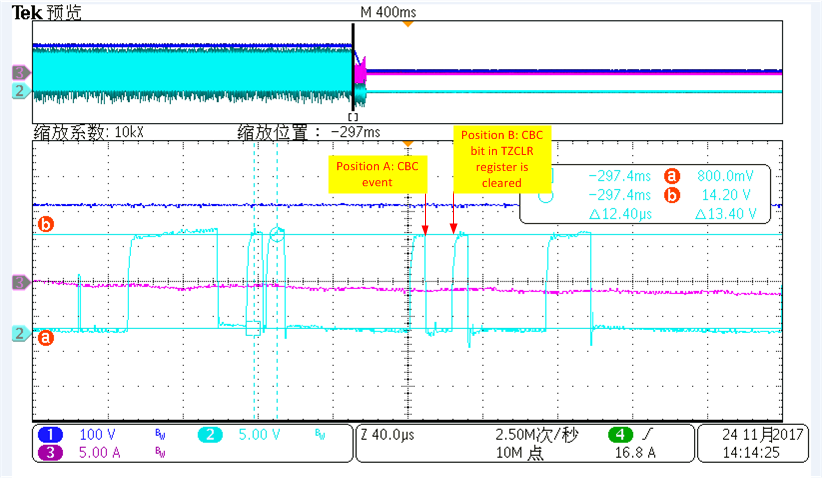
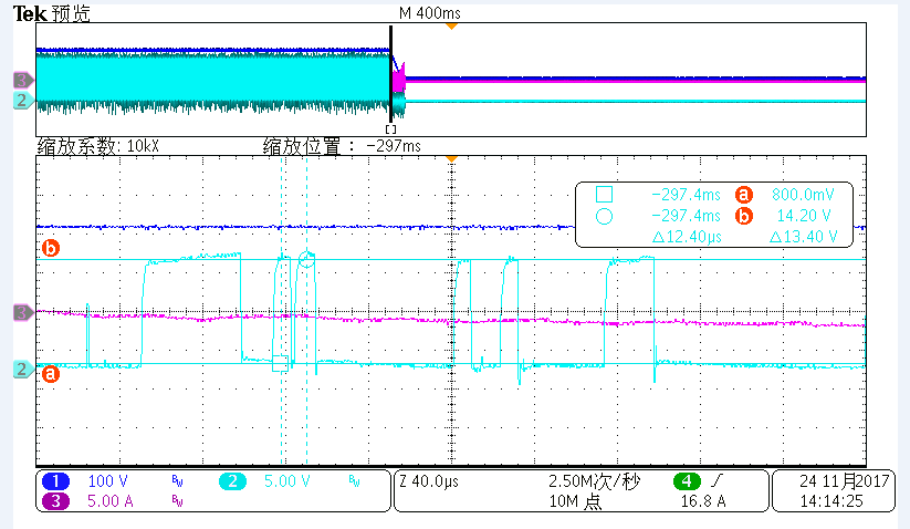
Here is my test wave, the normal pwm period is 50us, but the pwm cycle is changed after Clearing TZCLR register.

Here is my code about CBC initialization:


void init_pfc_acomp_trip_epwm(void)

{

    EALLOW;

    SysCtrlRegs.PCLKCR0.bit.ADCENCLK = 1;                 // Enable Clock to the ADC

    AdcRegs.ADCCTL1.bit.ADCBGPWD = 1;                     // Comparator shares the internal BG reference of the ADC, must be powered even if ADC is unused


    //enable analog comparator

    DELAY_US(1000);                                      // Delay for Power Up


    SysCtrlRegs.PCLKCR3.bit.COMP1ENCLK = 1;               // Enable clock to the Comparator 1 block

    Comp1Regs.COMPCTL.bit.COMPDACEN = 1;                  // Power up Comparator 1 locally

    //Comp1Regs.COMPCTL.bit.COMPSOURCE = 1;               // Connect the inverting input to pin COMP1B

    ////////////////Uncomment following 2 lines to use DAC instead of pin COMP1B //////////////////

    Comp1Regs.COMPCTL.bit.SYNCSEL = 1;                                              //Synchronous version of comparator output is passed

    Comp1Regs.COMPCTL.bit.QUALSEL = 31;                                             //Input to the block must be consistent for 3 consecutive clocks before output of Qual block can

                                                                                                                                      //change

    Comp1Regs.COMPCTL.bit.COMPSOURCE = 0;                 // Connect the inverting input to the internal DAC

    Comp1Regs.DACVAL.bit.DACVAL = COMP_DAC_VALUE;                     // Set DAC output to midpoint

    EDIS;


    EALLOW;

    // Define an event (DCAEVT1) based on TZ1 and TZ2

    EPwm1Regs.DCTRIPSEL.bit.DCAHCOMPSEL = DC_COMP1OUT;        // DCAH = Comparator 1 output

    EPwm1Regs.DCTRIPSEL.bit.DCALCOMPSEL = DC_TZ2;             // DCAL = TZ2

    //EPwm1Regs.TZDCSEL.bit.DCAEVT1 = TZ_DCAH_LOW;              // DCAEVT1 =  DCAH low(will become active as Comparator output goes low)

    //EPwm1Regs.DCACTL.bit.EVT1SRCSEL = DC_EVT1;                // DCAEVT1 = DCAEVT1 (not filtered)

    //EPwm1Regs.DCACTL.bit.EVT1FRCSYNCSEL = DC_EVT_ASYNC;       // Take async path


    EPwm1Regs.TZDCSEL.bit.DCAEVT2 = TZ_DCAH_LOW;

    EPwm1Regs.DCACTL.bit.EVT2SRCSEL = DC_EVT2; // DCAEVT2 = DCAEVT2 (not filtered)

    EPwm1Regs.DCACTL.bit.EVT2FRCSYNCSEL = DC_EVT_ASYNC; // Take async path // Enable DCAEVT2 as

    //a one shot trip source


    // Note: DCxEVT1 events can be define

    // Enable DCAEVT1 and DCBEVT1 are one shot trip sources

    // Note: DCxEVT1 events can be defined as one-shot.

    //       DCxEVT2 events can be defined as cycle-by-cycle.

    EPwm1Regs.TZSEL.bit.DCAEVT1 = 0;

    EPwm1Regs.TZSEL.bit.DCAEVT2 = 1;


    // What do we want the DCAEVT1 and DCBEVT1 events to do?

    // DCAEVTx events can force EPWMxA

    // DCBEVTx events can force EPWMxB

    EPwm1Regs.TZCTL.bit.TZA = TZ_FORCE_LO;           // EPWM1A will go high

    EDIS;

}


CBC handler code in ISR:

inline void epwm_cbc_handler(void)

{

    volatile union  TZFLG_REG tzflg;

    static int16 cbc_count = 0;


    EALLOW;

    tzflg.all = EPwm1Regs.TZFLG.all;

    if(tzflg.bit.CBC == 1) //CBC occurs

    {

        EPwm1Regs.TZCLR.all = tzflg.all; //clear cbc flag

        cbc_count ++;

        if(cbc_count == 5)

        {

            TURN_OFF_PFC();

            PFC_VCC_OFF;

            pfc_vars.cbc_fault = 1;

        }

    }

    else

    {

        cbc_count = 0;

    }

    EDIS;

}

Regards,

Jack

  • Jack,

    A normal use case for the TZ module is to get as fast of a response as possible. You may be able to do this if you configure the TZ to "Do nothing" then after 5 consecutive CBC trips reconfigure the TZ to "Clear Low" causing the PWM output to drive low.

    Regards,
    Cody 

  • Hi Jack,

    I would recommend that you configure every register bit in the TZCTL register.  The default settings for some of these bits likely are not doing what you want & may be contributing to what you are seeing.


    Thank you,
    Brett

  • Hi Cody,

    Thanks for your suggestion, but I don't think this is work around solution. If CBC occurs but pwm doesn't be tripped, then it will cause my IGBT damaged while output are shorted.

    Is there any other idea? Thanks...
  • Brett,

    Thanks for your suggestion. Can you please share the example code with me? I just copy it form epwm reference manual.
  • In the ePWM User's Guide, you'll find that there are 6 register bits in the TZCTL register. 

    You've currently only configured the TZA bit.  I'd configure the other register bits as 'Do Nothing'.  This will prevent them from affecting the output.

    ===

    If that doesn't help:
    Does clearing only the CBC flag change the behavior you see?  (instead of clearing all TZ flags)


    Thank you,
    Brett

  • Jack,

    Sorry, I misunderstood your problem. The CBC trip shouldn't clear in this situation. Have you configured the one-shot logic somewhere? Can you share the bit definitions of "tzflg.all"?

    I agree with Brett, a good next step would be to change "EPwm1Regs.TZCLR.all = tzflg.all; //clear cbc flag" to only clear the CBC flag. The way it's written now it could clear many flags. This may be OK for your program, but to simplify debug lets only clear the CBC flag.

    Regards,
    Cody 

  • Hi Cody,

    I just configure epwm wroks in CBC mode, no one-short required in this case.

    The bit definitions of tzflg.all are the same with TZFLG register.

    Here is my variable definition:
    volatile union TZFLG_REG tzflg;

    I have just verified your solution, there is no usage if I just clear CBC bit. The period of epwm is changed if the CBC bit in TZCLR register is cleared.

    Thanks..
  • Jack,
    could you share the offset address for tzflg and show the definition of TZFLG_REG?

    I don't understand "I have just verified your solution, there is no usage if I just clear CBC bit.". What do you mean by "no usage", does this mean that the code functions correctly when you only clear the CBC trip?

    How does the period change? Is it shorter or longer? I don't expect the PWM period to change due to a TZCLR"The period of epwm is changed if the CBC bit in TZCLR register is cleared."

    Regards,
    Cody
  • Hi Cody,

    Please note that my request is that epwm should be latched after 5 or 10 consecutive CBC occurs, and epwm should be tripped by CBC events.

    It seems that you still don't understand what issue I have gotten.  Please see below waveform that I have put some marks on it. The position A is the CBC events, I clear the CBC bit of TZCLR register at position B. It looks to me that EPWMxA was tripped by CBC, but EPWMxA pull high again after clearing the CBC bit in TZCLR register, this is not what I want. I want the EPWM turns on in next switch cycle instead of this cycle. Hope you've understood my situation.

    The definition of TZFLG_REG is in the DSP2802x_EPWM.h, here it is.

    //----------------------------------------------------

    // Trip zone flag register bit definitions */

    struct TZFLG_BITS {         // bits   description

      Uint16  INT:1;           // 0      Global status

      Uint16  CBC:1;           // 1      Trip Zones Cycle By Cycle Int

      Uint16  OST:1;           // 2      Trip Zones One Shot Int

      Uint16  DCAEVT1:1;       // 3      Force DCAEVT1 event

      Uint16  DCAEVT2:1;       // 4      Force DCAEVT2 event

      Uint16  DCBEVT1:1;       // 5      Force DCBEVT1 event

      Uint16  DCBEVT2:1;       // 6      Force DCBEVT2 event

      Uint16  rsvd2:9;         // 15:7   reserved

    };

    union TZFLG_REG {

      Uint16                  all;

      struct TZFLG_BITS       bit;

    };

  • Cody/Brett,

    Is there any update bout this issue? Thanks...
  • Hi Cody and Brett,

    Can you please help share some comments on this? Thanks...
  • Jack,

    sorry for the delay. Clearing the TZFLG.CBC will not affect the output of the PWM, the only event that clears a CBC trip is Counter=0. This feature is very well tested so I don't think there is a bug there.

    There are two things in this circuit that can also force the PWM output low, and be cleared at any point.

    1. The one-shot trip, if configured this can force the PWM low and writing to TZCLR.OSHT will clear the trip.
    2. The Digital compare event  (DCAEVT1, DCAEVT2, DCBEVT1 OR DCBEVT2) can force the PWM output low. If the comparator event is cleared then this will cause the trip event to clear at any point.

    If you made the modifications to your code suggested earlier in this thread, then I think that the Digital Compare event is forcing the PWM output low, not the CBC trip. 


    Regards,
    Cody 

  • Hi Cody,

    I know that CBC trip is well tested and works good, but what I need is that EPWM should force to low after 5 or 10 consecutive CBC occurs. Is it possible to do for this chip?
  • Jack,

    yes, you should be able to force the output low after x number of consecutive CBC trips.

    I would use a very similar scheme as to what you have tried:

    1. Setup the ePWMx ISR to interrupt at TBCTR = 0
    2. Disable all DCxEVTy
    3. Disable OSHT trips
    4. Set CBC trips to force low
    5. Write a ePWM ISR
      1. Increment a variable if the CBC flag is set else clear the variable
      2. If variable is > threshold reconfigure AQ or TZ to shutdown the PWM
      3. Clear the CBC flag
      4. Acknowledge interrupt

    Is anything unclear?

    Regards,
    Cody

  • Hi Cody,

    Thanks for your strong support. This issue has been fixed.

    Thanks again.

  • Jack,
    I am glad that your problem has been fixed.

    If you have any other issues please start another thread on the forum and we will gladly help!

    Regards,
    Cody