
- Ask a related questionWhat is a related question?A related question is a question created from another question. When the related question is created, it will be automatically linked to the original question.

Hello,
I'm encountering an unusual behaviour with the CBC trip zone and its operation on EPWMxA and EPWMxB
My code is configured to detect an overcurrent by using the ADC to sample several times within a PWM period and if the current is in excess of a threshold to trigger the CBC tripzone.
In general this is working well but I am noticing an unexplainable difference in the way it triggers PWMxA and PWMxB every now and then.
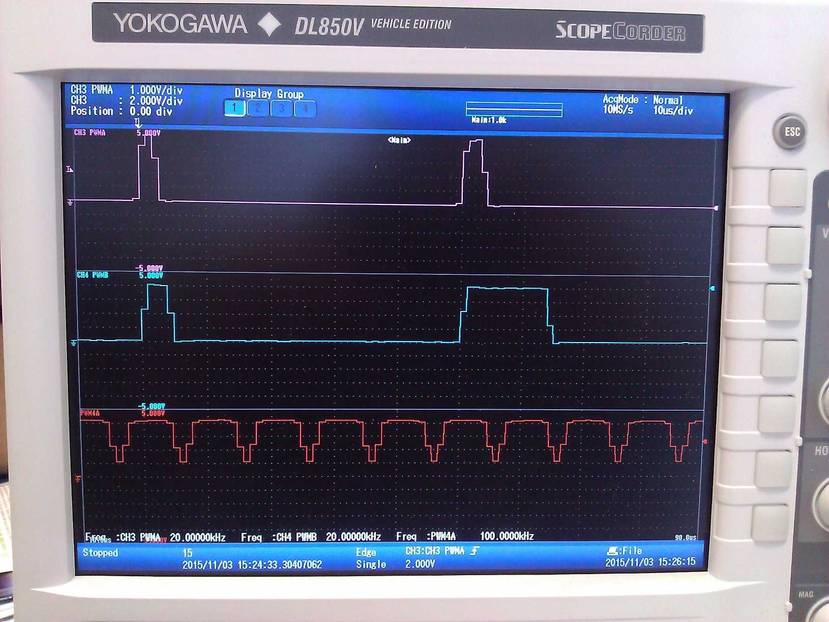
Ok, so looking at the outputs below, trace 3 is PWM1A and trace 4 is PWM1B trace 5 is concurrent with the SOCB trigger to sample the currents.
PWM1A is operating at 20kHz and the ADC sample rate is 100kHz. . The first response is pretty much as it should be, both PWM1A and PWM1B are going high, the overcurrent is being detected on the first sample and both are shutting down with the CBC trip zone event that is sent to PWM1. This is pretty much the way it is for most cycles. Occasionally you get on like the second pulse set and for some reason PWM1B seems to hang on until presumably there is a second trip zone trigger.
Any ideas as to what might be causing this?
The interrupt that triggers the CBC event is included below.
regards
steve
interrupt void seq2_int_isr(void)
{
//CpuTimer0Regs.TCR.bit.TRB = 1; // reload timer0 to time the interupt service
ADC2IntCount++;
// Service the ADC interrupt
// Values from Seq2 (IA, IB, IC and IDC) are read into the DMA automatically each time.
//T0_count1 = CpuTimer0Regs.TIM.half.LSW; // Latch lower 16-bits of timer0 (diagnostics)
// Get Analogue input value and process (N.B SEQ2 values in ADCRESULT8-11) only for testing....
ADCvalue2 = AdcMirror.ADCRESULT8; //Read first buffer register with zero wait state for IA
ADCvalue3 = AdcMirror.ADCRESULT9; //Read first buffer register with zero wait state for IB
ADCvalue4 = AdcMirror.ADCRESULT10; //Read first buffer register with zero wait state for IC
ADCvalue5 = AdcMirror.ADCRESULT11; //Read first buffer register with zero wait state for IDC - might use for DC current limit?
//Test the PWM curtailment function
if ((ADCvalue2 > HW_UPPER_CURRENT_LIMIT)||(ADCvalue2 < HW_LOWER_CURRENT_LIMIT)) { //simple threshold on Ia analogue input, quicker than converting for overcurrent tests?
EALLOW;
EPwm1Regs.TZFRC.bit.CBC = 0x01; //trigger a cycle by cycle TZ on PWM1 - Phase A
EDIS;
}
if ((ADCvalue3 > HW_UPPER_CURRENT_LIMIT)||(ADCvalue3 < HW_LOWER_CURRENT_LIMIT)) { //simple threshold on Ia analogue input, quicker than converting for overcurrent tests?
EALLOW;
EPwm2Regs.TZFRC.bit.CBC = 0x01; //trigger a cycle by cycle TZ on PWM2 - Phase B
EDIS;
}
if ((ADCvalue4 > HW_UPPER_CURRENT_LIMIT)||(ADCvalue4 < HW_LOWER_CURRENT_LIMIT)) { //simple threshold on Ia analogue input, quicker than converting for overcurrent tests?
EALLOW;
EPwm3Regs.TZFRC.bit.CBC = 0x01; //trigger a cycle by cycle TZ on PWM3 - Phase C
EDIS;
}
//Diagnostics - remove or comment out when ready
//T0_count2 = CpuTimer0Regs.TIM.half.LSW; // Latch lower 16-bits of timer0 (diagnostics)
//GpioDataRegs.GPATOGGLE.bit.GPIO8 = 1; // flip GPIO8 for testing purposes
// Reset the PWM SOCB flag
EPwm4Regs.ETCLR.bit.SOCB = 1; //Reset the SOCB flag
//reset the ADC units
AdcRegs.ADCTRL2.bit.RST_SEQ2 = 1; // Reset SEQ2 ready for the next SOCB trigger
AdcRegs.ADCST.bit.INT_SEQ2_CLR = 1; // Clear INT SEQ2 bit
// Acknowledge this interrupt to receive more interrupts from group 1
PieCtrlRegs.PIEACK.all = PIEACK_GROUP1; //Acknowledge interrupt from Any ADC
}


