Part Number: TMS320F28027
I draft an example code as below file, use PWM timer to trigger ADC sample, and implement both PWM and ADC interrupt.
The key point is PWM interrupt code will occupy long time to block the ADC interrupt, until ADC interrupt overlay flag is set, then clear the ADC overlay flag and release PWM interrupt to resume ADC interrupt.
//###########################################################################
//
// FILE:   Example_2802xAdcTempSensor.c
//
// TITLE:  f2802x ADC Temperature Sensor Example Program.
//
// ASSUMPTIONS:
//
//   This program requires the f2802x header files.
//
//   Make sure the CPU clock speed is properly defined in
//   f2802x_Examples.h before compiling this example.
//
//
//    $Boot_Table
//    While an emulator is connected to your device, the TRSTn pin = 1,
//    which sets the device into EMU_BOOT boot mode. In this mode, the
//    peripheral boot modes are as follows:
//
//      Boot Mode:   EMU_KEY        EMU_BMODE
//                   (0xD00)	     (0xD01)
//      ---------------------------------------
//      Wait		 !=0x55AA        X
//      I/O		     0x55AA	         0x0000
//      SCI		     0x55AA	         0x0001
//      Wait 	     0x55AA	         0x0002
//      Get_Mode	 0x55AA	         0x0003
//      SPI		     0x55AA	         0x0004
//      I2C		     0x55AA	         0x0005
//      OTP		     0x55AA	         0x0006
//      Wait		 0x55AA	         0x0007
//      Wait		 0x55AA	         0x0008
//      SARAM		 0x55AA	         0x000A	  <-- "Boot to SARAM"
//      Flash		 0x55AA	         0x000B
//	    Wait		 0x55AA          Other
//
//   Write EMU_KEY to 0xD00 and EMU_BMODE to 0xD01 via the debugger
//   according to the Boot Mode Table above. Build/Load project,
//   Reset the device, and Run example
//
//   $End_Boot_Table
//
//
// Description:
//
//   This example sets up the PLL in x12/2 mode.
//
//   For 60 MHz devices (default)
//   (assuming a 10Mhz input clock).
//
//   Interrupts are enabled and the ePWM1 is set up to generate a periodic
//   ADC SOC interrupt - ADCINT1. One channel is converted -  ADCINA5, which is
//	 internally connected to the temperature sensor.
//
//   Watch Variables:
//
//         TempSensorVoltage[10] Last 10 ADCRESULT0 values
//         ConversionCount  Current result number 0-9
//         LoopCount        Idle loop counter
//
//
//###########################################################################
// $TI Release: F2802x Support Library v230 $
// $Release Date: Fri May  8 07:43:05 CDT 2015 $
// $Copyright: Copyright (C) 2008-2015 Texas Instruments Incorporated -
//             http://www.ti.com/ ALL RIGHTS RESERVED $
//###########################################################################

#include "DSP28x_Project.h"     // Device Headerfile and Examples Include File

// Prototype statements for functions found within this file.
__interrupt void adc_isr(void);
__interrupt void epwm1_isr(void);

// Global variables used in this example:
uint16_t LoopCount;
uint16_t ConversionCount;
uint16_t TempSensorVoltage[10];
uint16_t EPWMTEST_FLAG;
uint16_t EPWMTEST_COUNTER,EPWMLOOP_COUNTER;

void main()
{
// WARNING: Always ensure you call memcpy before running any functions from RAM
// InitSysCtrl includes a call to a RAM based function and without a call to
// memcpy first, the processor will go "into the weeds"
   #ifdef _FLASH
	memcpy(&RamfuncsRunStart, &RamfuncsLoadStart, (size_t)&RamfuncsLoadSize);
   #endif

// Step 1. Initialize System Control:
// PLL, WatchDog, enable Peripheral Clocks
// This example function is found in the f2802x_SysCtrl.c file.
   InitSysCtrl();

// Step 2. Initialize GPIO:
// This example function is found in the f2802x_Gpio.c file and
// illustrates how to set the GPIO to it's default state.
// InitGpio();  // Skipped for this example

// Step 3. Clear all interrupts and initialize PIE vector table:
// Disable CPU interrupts
   DINT;

// Initialize the PIE control registers to their default state.
// The default state is all PIE interrupts disabled and flags
// are cleared.
// This function is found in the f2802x_PieCtrl.c file.
   InitPieCtrl();

// Disable CPU interrupts and clear all CPU interrupt flags:
   IER = 0x0000;
   IFR = 0x0000;

// Initialize the PIE vector table with pointers to the shell Interrupt
// Service Routines (ISR).
// This will populate the entire table, even if the interrupt
// is not used in this example.  This is useful for debug purposes.
// The shell ISR routines are found in f2802x_DefaultIsr.c.
// This function is found in f2802x_PieVect.c.
   InitPieVectTable();

// Interrupts that are used in this example are re-mapped to
// ISR functions found within this file.
   EALLOW;  // This is needed to write to EALLOW protected register
   PieVectTable.ADCINT3 = &adc_isr;
   PieVectTable.EPWM1_INT = &epwm1_isr;
   EDIS;    // This is needed to disable write to EALLOW protected registers

// Step 4. Initialize the ADC:
// This function is found in f2802x_Adc.c
   InitAdc();  // For this example, init the ADC
   AdcOffsetSelfCal();

// Step 5. Configure ADC to sample the temperature sensor on ADCIN5:
// The output of Piccolo temperature sensor can be internally connected to the ADC through ADCINA5
// via the TEMPCONV bit in the ADCCTL1 register. When this bit is set, any voltage applied to the external
// ADCIN5 pin is ignored.
   EALLOW;
   AdcRegs.ADCCTL1.bit.TEMPCONV 	= 1;	//Connect internal temp sensor to channel ADCINA5.
   EDIS;

// Step 6. Continue configuring ADC to sample the temperature sensor on ADCIN5:
// Since the temperature sensor is connected to ADCIN5, configure the ADC to sample channel ADCIN5
// as well as the ADC SOC trigger and ADCINTs preferred. This example uses EPWM1A to trigger the ADC
// to start a conversion and trips ADCINT1 at the end of the conversion.

//Note: The temperature sensor will be double sampled to apply the workaround for rev0 silicon errata for the ADC 1st sample issue
   EALLOW;
   AdcRegs.ADCCTL1.bit.INTPULSEPOS	= 1;	//ADCINT1 trips after AdcResults latch
   AdcRegs.INTSEL3N4.bit.INT3E     = 1;	    //Enabled ADCINT1
   AdcRegs.INTSEL3N4.bit.INT3CONT  = 0;	    //Disable ADCINT1 Continuous mode
   AdcRegs.INTSEL3N4.bit.INT3SEL	= 1;	//setup EOC1 to trigger ADCINT1 to fire
   AdcRegs.ADCSOC0CTL.bit.CHSEL 	= 5;	//set SOC0 channel select to ADCINA5 (which is internally connected to the temperature sensor)
   AdcRegs.ADCSOC1CTL.bit.CHSEL 	= 5;	//set SOC1 channel select to ADCINA5 (which is internally connected to the temperature sensor)  errata workaround
   AdcRegs.ADCSOC0CTL.bit.TRIGSEL 	= 5;	//set SOC0 start trigger on EPWM1A
   AdcRegs.ADCSOC1CTL.bit.TRIGSEL 	= 5;	//set SOC1 start trigger on EPWM1A errata workaround
   AdcRegs.ADCSOC0CTL.bit.ACQPS 	= 36;	//set SOC0 S/H Window to 37 ADC Clock Cycles, (36 ACQPS plus 1)
   AdcRegs.ADCSOC1CTL.bit.ACQPS 	= 36;	//set SOC1 S/H Window to 37 ADC Clock Cycles, (36 ACQPS plus 1) errata workaround
   EDIS;

// Step 7. User specific code, enable interrupts:
// Enable ADCINT1 in PIE
   PieCtrlRegs.PIEIER10.bit.INTx3 = 1;	// Enable INT 1.1 in the PIE
   PieCtrlRegs.PIEIER3.bit.INTx1 = 1;   // Enable EPWM INTn in the PIE: Group 3 interrupt 1-3
   IER |= M_INT10; 						// Enable CPU Interrupt 1
   IER |= M_INT3;   // Enable CPU INT3 which is connected to EPWM1-3 INT:
   EINT;          						// Enable Global interrupt INTM
   ERTM;          						// Enable Global realtime interrupt DBGM

   LoopCount = 0;
   ConversionCount = 0;

// Assumes ePWM1 clock is already enabled in InitSysCtrl();
   EPwm1Regs.ETSEL.bit.SOCAEN	= 1;		// Enable SOC on A group
   EPwm1Regs.ETSEL.bit.SOCASEL	= 4;		// Select SOC from from CPMA on upcount
   EPwm1Regs.ETPS.bit.SOCAPRD 	= 1;		// Generate pulse on 1st event
   EPwm1Regs.CMPA.half.CMPA 	= 0x0080;	// Set compare A value
   EPwm1Regs.TBPRD 				= 0xFFFF;	// Set period for ePWM1
   EPwm1Regs.TBCTL.bit.CTRMODE 	= 0;		// count up and start

   // Interrupt where we will modify the deadband
   EPwm1Regs.ETSEL.bit.INTSEL = ET_CTR_ZERO;      // Select INT on Zero event
   EPwm1Regs.ETSEL.bit.INTEN = 1;                 // Enable INT
   EPwm1Regs.ETPS.bit.INTPRD = ET_3RD;            // Generate INT on 3rd event

// Wait for ADC interrupt
   for(;;)
   {
      LoopCount++;
   }
}

__interrupt void epwm1_isr(void)
{
	while (!AdcRegs.ADCINTOVF.bit.ADCINT3){
		EPWMTEST_COUNTER++;
	}
	AdcRegs.ADCINTOVFCLR.bit.ADCINT3 = 1;

	EPWMLOOP_COUNTER++;

	   // Clear INT flag for this timer
	   EPwm1Regs.ETCLR.bit.INT = 1;

	   // Acknowledge this interrupt to receive more interrupts from group 3
	   PieCtrlRegs.PIEACK.all = PIEACK_GROUP3;
}

__interrupt void  adc_isr(void)
{
  TempSensorVoltage[ConversionCount] = AdcResult.ADCRESULT1;  //discard ADCRESULT0 as part of the workaround to the 1st sample errata for rev0

  // If 20 conversions have been logged, start over

      ConversionCount++;

  AdcRegs.ADCINTFLGCLR.bit.ADCINT3 = 1;		//Clear ADCINT1 flag reinitialize for next SOC
  PieCtrlRegs.PIEACK.all = PIEACK_GROUP10;   // Acknowledge interrupt to PIE

  return;
}
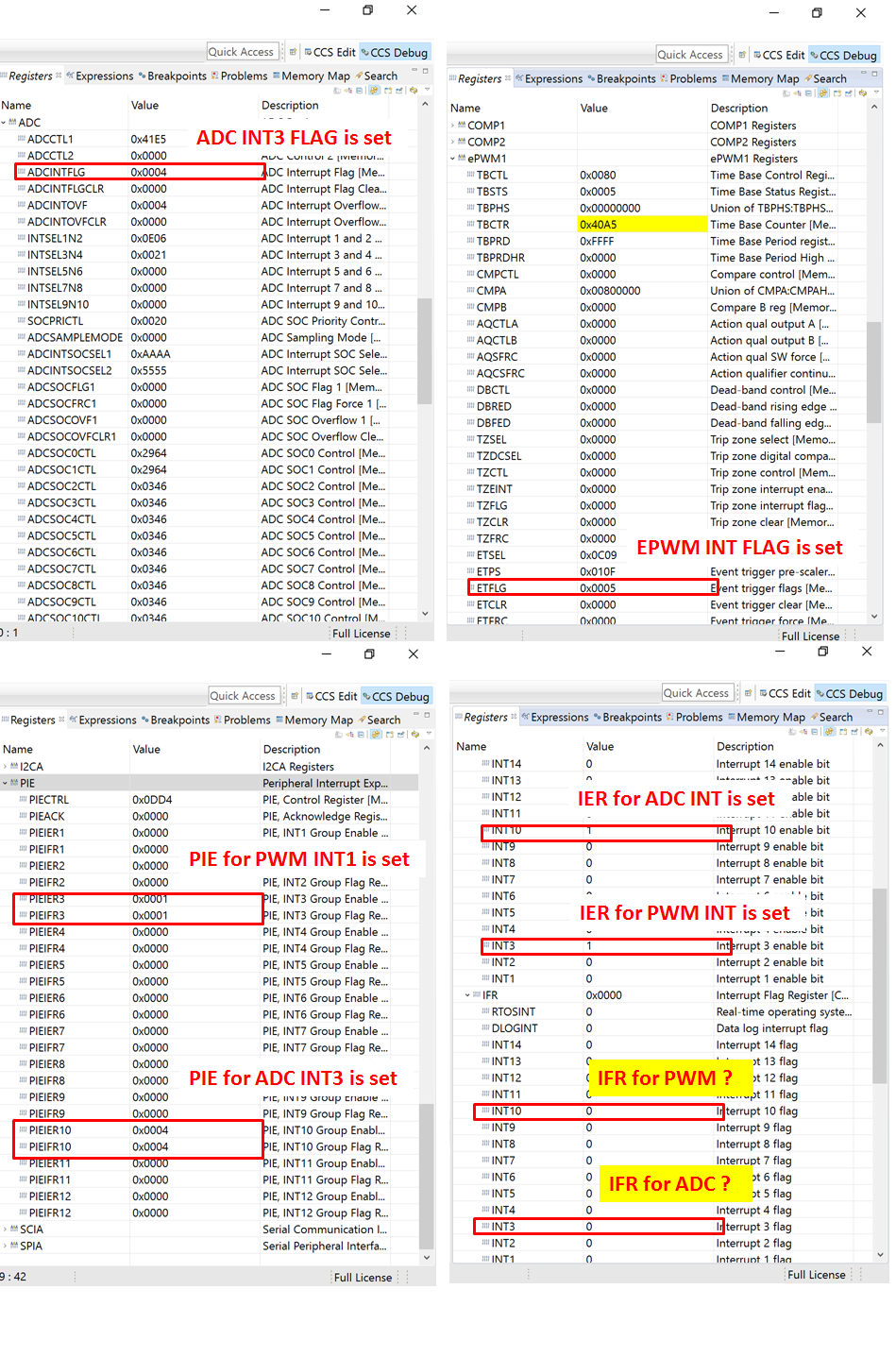
However after run a while on TI LaunchPad, both the PWM and ADC stop to jump into interrupt functions.
I double confirm the register that ADC/PWM interrupt flag is set and enable, the PIE flag is also set and enable, the IER is also enable, however the IFR is not be set.
I doubt if it is something wrong in the C2000 interrupt hardware, may I appreciate your help check and advice?