
- Ask a related questionWhat is a related question?A related question is a question created from another question. When the related question is created, it will be automatically linked to the original question.
Hi,
I have a problem with my EPwm signal, or maybe it is the problem with my ADC? I am new in this stuff and it is hard to tell for me what I am doing wrong. First I just wanted to start EPwm in any configuration and it looked like it worked, I used it to control brightness of a diode. But then I wanted to check how it actually looks so I connected it with a wire with Adc to see its trajectory in CCS Debug mode. This is what i got:
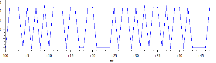
I dont think this is a good result, I belive it should be perfectly steady, meanwhile what i got looks like a total chaos, when i refresh the results it sometimes gets even wierder,
Here are the properties of the graph in CCS:

And here is my code:
#include "F28x_Project.h"


void Init_EPwm2Gpio(void);
void Init_Clocks(void);
void Configure_EPwm2Regs(void);
void Configure_ADC(void);
void Configure_EPWM_trig_ADC(void);
void SetupADCEpwm(Uint16 channel);


#define RESULTS_BUFFER_SIZE 256

Uint16 AdcaResults[RESULTS_BUFFER_SIZE];
Uint16 resultsIndex;
volatile Uint16 bufferFull;

int main(void)
{


    InitSysCtrl();                              //inicjalizacja zegarow, watchdoga, pll itp.  // Nie wnikałem za bardzo

    Init_EPwm2Gpio();                            // konfiguracja gpio do epwm2
    Init_Clocks();
    Configure_EPwm2Regs();                           // Konfiguracja epwm2


    //////////////////////////////////////////////////////////////////////////////  Here's the part I don't really understand but I belive this is not a case here ////////////////
        DINT;
        InitPieCtrl();

        IER = 0x0000;
        IFR = 0x0000;

        InitPieVectTable();
        //////////////////////////////////////////////////////////////////////////////////////////////////////////////////////////


        Configure_ADC();
        Configure_EPWM_trig_ADC();
        SetupADCEpwm(2);


    for(;;)
        {
        AdcaResults[resultsIndex++] = AdcaResultRegs.ADCRESULT1;
            if(RESULTS_BUFFER_SIZE <= resultsIndex)
            {
                resultsIndex = 0;
                bufferFull = 1;
            }
        }
}

void Init_EPwm2Gpio()
{
    EALLOW;
    GpioCtrlRegs.GPAPUD.bit.GPIO2 = 1;    // Disable pull-up on GPIO2 (EPWM2A)
    GpioCtrlRegs.GPAPUD.bit.GPIO3 = 1;    // Disable pull-up on GPIO3 (EPWM2B)

        // Configure EPwm-2 pins using GPIO regs
        // This specifies which of the possible GPIO pins will be EPWM2 functional pins.
    GpioCtrlRegs.GPAMUX1.bit.GPIO2 = 1;   // Configure GPIO2 as EPWM2A
    GpioCtrlRegs.GPAMUX1.bit.GPIO3 = 1;   // Configure GPIO3 as EPWM2B
    EDIS;
}

void Init_Clocks()
{
    EALLOW;
    CpuSysRegs.PCLKCR0.bit.TBCLKSYNC = 1;       //When set PWM time bases of all the PWM modules start counting.
    CpuSysRegs.PCLKCR2.bit.EPWM2=1;             // epwm clock enable
    CpuSysRegs.PCLKCR2.bit.EPWM1=1;             // epwm1 wyzwala adc, epwm2 do diody
    CpuSysRegs.PCLKCR13.bit.ADC_A = 1;
    EDIS;
}

void Configure_EPwm2Regs()
{
    EPwm2Regs.TBCTL.bit.CTRMODE = TB_COUNT_UP;          // liczenie w gore
    EPwm2Regs.TBPRD = 5000;                             // Przy 200MHz taktowania plytki, podzieleniu przez cztery (2*2), okres 5000 powinien dac 100us podstawy
    EPwm2Regs.TBPHS.bit.TBPHS = 0;                      // faza rowna 0
    EPwm2Regs.TBCTR = 0;                                // resetowanie licznika
    EPwm2Regs.TBCTL.bit.HSPCLKDIV = TB_DIV2;
    EPwm2Regs.TBCTL.bit.CLKDIV = TB_DIV2;               // oba dziela przez dwa, lacznie przez cztery

    EPwm2Regs.CMPCTL.bit.SHDWAMODE = 0x0;//CC_IMMEDIATE;
    EPwm2Regs.CMPCTL.bit.SHDWBMODE = 0x0;//CC_IMMEDIATE;
    EPwm2Regs.CMPCTL.bit.LOADAMODE = CC_CTR_ZERO;
    EPwm2Regs.CMPCTL.bit.LOADBMODE = CC_CTR_ZERO;


    EPwm2Regs.CMPA.bit.CMPA = 2500;                      // counter compare
    EPwm2Regs.AQCTLA.bit.PRD = AQ_CLEAR;                // zeruj pwma na poczatku okresu
    EPwm2Regs.AQCTLA.bit.CAU = AQ_SET;                  // jak CC jest rowny lincznikowi PWM to ustalam akcje, w tym przypadku stan wysoki

}

void Configure_ADC(void)
{
    EALLOW;

    //write configurations
    AdcaRegs.ADCCTL2.bit.PRESCALE = 6; //set ADCCLK divider to /4
    AdcSetMode(ADC_ADCA, ADC_RESOLUTION_12BIT, ADC_SIGNALMODE_SINGLE);

    //Set pulse positions to late
    AdcaRegs.ADCCTL1.bit.INTPULSEPOS = 1;

    //power up the ADC
    AdcaRegs.ADCCTL1.bit.ADCPWDNZ = 1;

    //delay for 1ms to allow ADC time to power up
    DELAY_US(1000);

    EDIS;
}

void Configure_EPWM_trig_ADC(void)
{
    EALLOW;
    EPwm1Regs.TBCTL.bit.CTRMODE = TB_COUNT_UP;
    EPwm1Regs.TBPRD = 0x1000;// Set period to 4096 counts
    EPwm1Regs.CMPA.bit.CMPA = 0x0800;     // Set compare A value to 2048 counts

    EPwm1Regs.ETSEL.bit.SOCAEN = 1;    // Enable SOC on A group
    EPwm1Regs.ETSEL.bit.SOCASEL = 4;   // 100: Enable event time-base counter equal to CMPA when the timer is incrementing or CMPC when the timer is incrementing
    EPwm1Regs.ETPS.bit.SOCAPRD = 1;       // Generate pulse on 1st event
    EDIS;
}


void SetupADCEpwm(Uint16 channel)
{
    Uint16 acqps;

    //
    //determine minimum acquisition window (in SYSCLKS) based on resolution
    //
    if(ADC_RESOLUTION_12BIT == AdcaRegs.ADCCTL2.bit.RESOLUTION)
    {
        acqps = 14; //75ns
    }
    else //resolution is 16-bit
    {
        acqps = 63; //320ns
    }


    EALLOW;
    AdcaRegs.ADCSOC1CTL.bit.CHSEL = channel;  //wybierajac channel=2, SOC1 bedzie pobierac wartosc z adcina2 i zapisywac je w adcresult1
    AdcaRegs.ADCSOC1CTL.bit.ACQPS = acqps; //sample window is 100 SYSCLK cycles
    AdcaRegs.ADCSOC1CTL.bit.TRIGSEL = 5; //trigger on ePWM1 SOCA/C
    EDIS;
}


