


Good afternoon, I'm trying to achieve a 0% or 100% duty cycle using the values of CMP and AQCTLA.bit.ZRO. However, I get strange behavior.
void InitEPwm1(void)
{
    // Setup TBCLK
    // Set Time-Base Period register according to PWM frequency.
    // Set time-base counter phase to 0.
    // Clear time-base counter.
    EPwm1Regs.TBPRD = PWM_TBPRD; // 12500 for 8kHz
    EPwm1Regs.TBPHS.bit.TBPHS = 0x0000;
    EPwm1Regs.TBCTR = 0x0000;

    // Clear Compare values
    EPwm1Regs.CMPA.all = 0;
    EPwm1Regs.CMPB.all = 0;
    EPwm1Regs.CMPC = 0;
    EPwm1Regs.CMPD = 0;

    // Setup Counter Mode
    // Set Counter Mode to Up-down count mode.
    // Do not load the time-base counter (TBCTR) from the time-base phase
    // register (TBPHS).
    // Sync output when Time-base counter equal to zero (TBCTR = 0x00)
    // Set High Speed Time Base Clock Pre-Scale to 1.
    // Set Time Base Clock Pre-Scale to 1.
    // TBCLK = EPWMCLK/(HSPCLKDIV * CLKDIV)
    EPwm1Regs.TBCTL.bit.CTRMODE = TB_COUNT_UPDOWN;
    EPwm1Regs.TBCTL.bit.PHSEN = TB_DISABLE;
    EPwm1Regs.TBCTL.bit.SYNCOSEL = TB_CTR_ZERO;
    EPwm1Regs.TBCTL.bit.HSPCLKDIV = TB_DIV1;
    EPwm1Regs.TBCTL.bit.CLKDIV = TB_DIV1;

    // Setup the deadband
    // Active Low complementary PWM
    // DB is fully enabled
    // Active low complementary mode
    // EPWM1A is the source for both falling and rising edge delay.
    // Dead-band time is 2.5us ( 500 / TBCLK)
    EPwm1Regs.DBCTL.bit.OUT_MODE = DB_FULL_ENABLE;
    EPwm1Regs.DBCTL.bit.POLSEL = DB_ACTV_LOC;
    EPwm1Regs.DBCTL.bit.IN_MODE = DBA_ALL;
    EPwm1Regs.DBFED = 500;
    EPwm1Regs.DBRED = 500;

    // Setup shadowing
    // Use shadowing for CMPA, AQCTLA registers.
    // Load from shadow to active when Time-base counter equal to zero.
    EPwm1Regs.CMPCTL.bit.SHDWAMODE = CC_SHADOW;
    EPwm1Regs.AQCTL.bit.SHDWAQAMODE = AQ_SHADOW;
    EPwm1Regs.CMPCTL.bit.LOADAMODE = CC_CTR_ZERO;
    EPwm1Regs.AQCTL.bit.LDAQAMODE = AQ_CTR_ZERO;

    // Clear actions
    EPwm1Regs.AQCTLA.bit.CAU = AQ_TOGGLE;
    EPwm1Regs.AQCTLA.bit.CAD = AQ_TOGGLE;
    EPwm1Regs.AQCTLA.bit.ZRO = AQ_NO_ACTION;
    EPwm1Regs.AQCTLA.bit.PRD = AQ_NO_ACTION;

    // Go
    EPwm1Regs.AQCTLA.bit.ZRO = AQ_CLEAR;
    EPwm1Regs.CMPA.bit.CMPA = PWM_TBPRD;
}
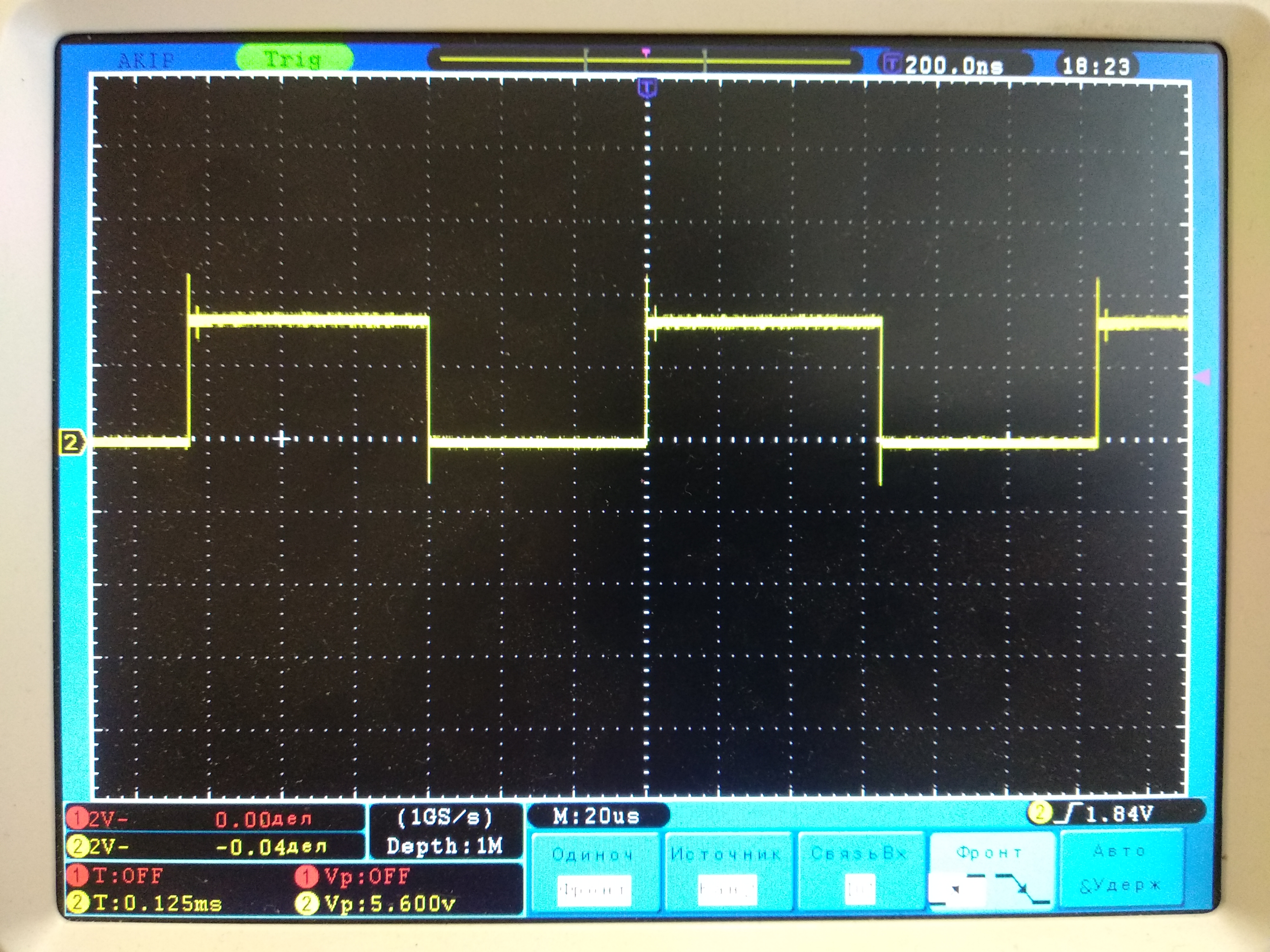
Why i see toggle at PRD?
if i set EPwm1Regs.CMPA.bit.CMPA = 0 i see toggle at zero,
if i set EPwm1Regs.CMPA.bit.CMPA = PWM_TBPRD + some value i still see toggle at period
this is a little inconsistent with what is written in SPRUHM8I page 1896
