This thread has been locked.
If you have a related question, please click the "Ask a related question" button in the top right corner. The newly created question will be automatically linked to this question.
Hello,
This thread came from: https://e2e.ti.com/support/microcontrollers/c2000/f/171/t/668112
Unfortunately, all the ADC inputs are occupied. So they can‘t assign the internal ADC inputs for duplication.
Under the constraint, is it possible to advice? My idea would be, put more ADC for diagnosis.
My customer questions are:
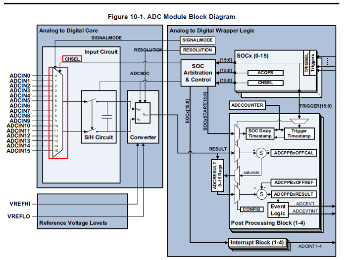
Q1. We think the # of ADC MUX address signals is four. Is it correct ?
Q2. Do you have an executable advice for my customer situation? I would explain my customer situation as follows:
[Customer situation]
All the ADC inputs are occupied, so they would like to put diagnostics for all the ADC multiplexer inputs.
Here the word ‘diagnostics’ means IEC60730 Table H.1 -- 7.2.2 Analog multiplexer -- Class B wrong addressing -- Plausibility check.
They read the requirement is, under the multiplexer fault, the fault is detected and the safety is kept.
Assuming the # of multiplexer address line is four, they would like to detect a single line fault (fix to high or low)
Hi Hideaki,
ADC Mux is only one component of the overall ADC module. Other ADC module sub-parts includes S/H, ADC converter, Configuration/Results registers, Ref voltage, Arbitration and control, IO pads etc. which can also contribute to failure rate of ADC conversion. In order to safe/cover the entire conversion of input signal to results register, we recommend the ‘Hardware Redundancy’ as safety mechanism, where a signal input is redundantly converted by 2 individual ADC’s and then followed by comparison of results, either by internal or external input connection. This will detect both types of faults, Permanent (e.g. stuck-at) as well as Transient (e.g. SER bit-flips in control registers) errors. It may not be feasible to take the module offline during application run time for periodic pattern testing and ‘Hardware Redundancy’ will serve for continuous online diagnostic to detect faults (necessary and sufficient).
In order to test the test the functionality of the entire chain using a test pattern, lets say only at startup for detecting latent(permanent) faults, will require to have control of the inputs. Currently only select inputs of all four ADC are controllable from within MCU using DACOUT, to test all the mux combinations will require taking control of the input IO pad from external to MCU.
Other than Hardware Redundancy, we have below suggested safety mechanisms for detecting faults in ADC module and are described in Safety Manual.
ADC3 - ADC Information Redundancy Techniques
- The correlation between input signals can be used to check the integrity (for example, if the three phase voltage, V1, V2, V3 is being measured using ADC, the function V1 + V2 + V3 = 0 can be used to provide diagnostic coverage for input signal integrity and ADC conversion).
ADC8 - ADC Input Signal Integrity Check
- Plausibility of input signal check using built in HW mechanism
ADC4 - Opens/Shorts Detection Circuit for ADC
- Detect faults in the ADC input channel.
ADC6 - Periodic Software Read Back of Static Configuration Registers
- Faults in CHSEL,ACQPS registers etc can be detected
ADC7 - ADC Signal Quality Check by Varying Acquisition Window
- Varying amount of time the sampling capacitors allowed to charge
Regards,
- Ashish