This thread has been locked.
If you have a related question, please click the "Ask a related question" button in the top right corner. The newly created question will be automatically linked to this question.
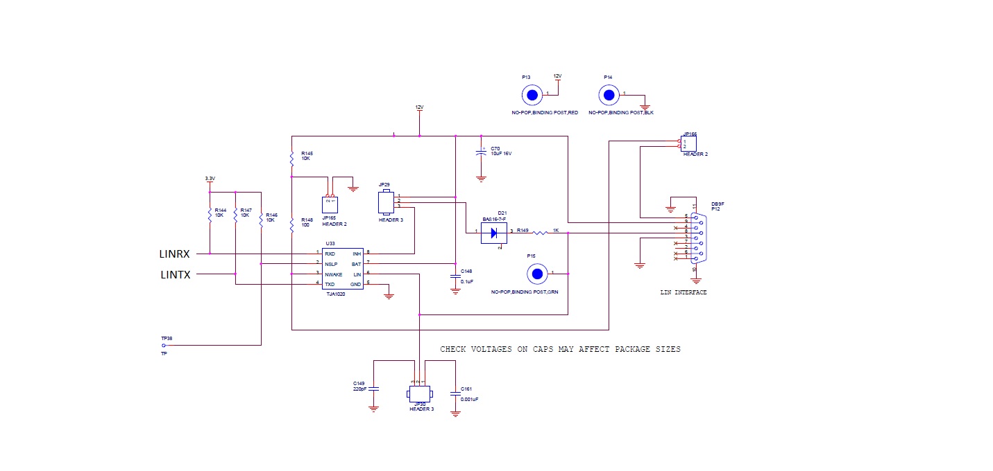
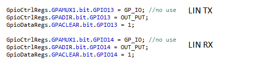
I cannot find any decent literature on how to wire LIN TX or RX to get signals out. Can someone please help me I've blown two boards and cannot figure out why. Below is a diagram of the connection. I was thinking the loop back was blowing it up. The pins are not used in the GPIO and are currently configured as outputs They will be activated but I need to stop destroying things.
How do I correctly hook this thing up?
Thanks
We do not have a transceiver in the circuit. I did not think we needed one but now I am guess that is a yes. I cannot understand how we fried a chip however. Was it because of the loopback? Can you possible explain that? Here is what were were using. We are going to change the GPIO but did not have the code yet written. I cannot find any decent literature besides the TMS320F2803x_LIN doc (rature Number: SPRUGE2B) But this does not explain the needed circuitry.
Thanks
Bill
William,
It would be hard for me to figure out why the chip got fried without access to the schematics and your test code.
Please check http://www.ti.com/interface/can-lin/products.html#p1389=LIN for TI's LIN portfolio.
Isolation is typically done at the MCU boundary.
For questions related to transceivers, isolation etc, please visit our "Industrial Interface" engineering forum e2e at: e2e.ti.com/.../ .
Please download the Application Report titled "LIN Protocol and Physical Layer Requirements" (SLLA383) from the TI website. That should answer your questions.
If you have no more outstanding issues, please close the post.