This thread has been locked.

If you have a related question, please click the "Ask a related question" button in the top right corner. The newly created question will be automatically linked to this question.

CCS/TMS320F28379D: TMS320F28379D High Resolution Period and High Resolution Deadband sample code

Part Number: TMS320F28379D

Tool/software: Code Composer Studio

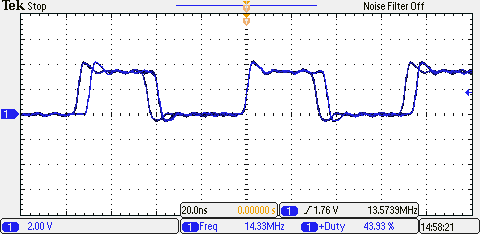
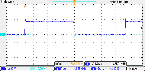
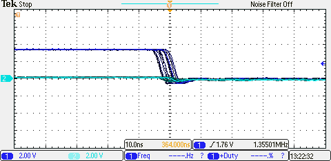
Is a sample code available for High Resolution Period and High Resolution Deadband control for a Delfino TMS320F28379D. I have tried to modify the example code hrpwm_deadband_sfo_v8.c without luck. I need to operate a full bridge inverter (H-bridge with the second bridge 180 degree phase shifted) at 13.56 MHz with 50% duty cycle and deadband control. The frequency and deadband need to be able to be finely adjustable with the high resolution of the Delfino controller. Thank you.

  • Hi Brandon,

    Based on this similar e2e thread:
    e2e.ti.com/.../666648

    I believe this should be possible, but we don't have any example code.

    Can you be a little more specific on how what you have been able to get working? Have you been able to also get high-resolution period control working, but you are having trouble getting both to work at once? Or you haven't been able to get HR period control to work at all?
  • Hi Devin,

    Yes, I could not get the high-resolution period control to work. I have abandoned trying to modify the example code. Instead, I'm using simulink to build the code. I have been able to generate a PWM with an average frequency of 13.57 MHz (shown in black in the attached images), but a 5 ns jitter is seen that changes the instantaneous frequency and duty cycle to 13.36 MHz and 40.78% (shown in blue in the attached image) and 14.33 MHz and 43.93% (shown in blue in the other attached image). I have attached the simulink model and c code generated. Is there a selection in simulink or a line needed in the c code to alleviate this?

    codegen.zip

  • Hi Brandon,

    You can get jitter if you generate a sync out pulse.  It looks like in your code, SYNCOSEL = 3, which means that the sync out signal is controlled by TBCTL2.SYNCOSELX.  I didn't see the configuration of this register in the code you attached, so you might want to check if the code is setup to generate a sync out on CMPC or CMPD.

  • Hi Devin,

    Thank you very much. I made SYNCOSEL = 0 by changing in the Simulink model in the ePWM7 block under the General tab, setting Synchronization output (SYNCO) to 'Pass through (EPWMxXYNCI or SWFSYNC)'. Doing that plus setting under the HRPWM tab the High resolution PWM (HRPWM) Load mode on ePWMxA: 'Counter equals to zero (CTR=ZERO)', High resolution PWM (HRPWM) control mode on ePWMxA: 'Duty or Period control mode', and High resolution PWM (HRPWM) edge control mode on ePWMxA: 'Rising Edge', fixes the jittering frequency. All that is left the duty cycle is jittering from 37% to 43% (shown in the attached figures) even though it is set at 50%. Any suggestions on how to resolve this, preferably in simulink? Thanks so much!

    6114.codegen.zip

  • One suggestion I pulled from MATLAB Answers:

    This is specific to the F28379D LaunchPad, but I am wondering if a similar issue on oscillator frequency mismatch may be occurring with the ControlCard.  I looks like it would be worth a quick check.

    The oscillator frequency must match the LaunchPad's external oscillator frequency. While the F28379D has an internal crystal that oscillates at 20MHz, the LaunchPad also has an external oscillator that runs at 10MHz. Simulink's default value is 20MHz. This setting is appropriate when working with the F28379D alone. However, this frequency value can cause problems when using external mode on a LaunchPad. Please go to Hardware Implementation -> Device details -> Clocking and change the value of "Oscillator clock (OSCCLK) frequency in MHz" from 20 to 10.

    If this didn't help and you are still stuck, please contact MathWorks Technical Support for assistance.

    Cheers,

    -Brian

  • Setting the OSCCLK clock frequency to 10 MHz (along with SYSPLLMULT=20 and SYSDIVSEL=1) makes the controller put out no signal at all. Please advise.
  • Hi Brandon,

    I didn't find any other suggestion and my Developer is out this week.  Please contact MathWorks Technical Support for assistance.

    Thanks,

    -Brian

  • Hi Brandon,

    13+ MHz is definitely pushing what this module is designed to do.  Does this run OK if you reduce the frequency by a factor of 10?

    In the TRM, we loosely state that 5MHz is about the max for 100MHz ePWM clock.  

  • Hi Devin,

    I ran the controller at 1.355 MHz and the PWM looks much better. I noticed there is still a jitter on the PWM duty cycle, 48.82% to 49.41%, as shown in the images. This of course is negligible. I zoomed in on the waveform though and it looks just like the jitter observed at 13.56 MHz, as shown in the image. Is this jitter always present, but is just negligible at lower operating frequencies? Thank you for looking into this.

  • Hi Brandon,

    I don't think you shouldn't be seeing jitter like this. Are you constantly calling the SFO library? Re-calibrating really frequently could result in some jitter as slightly different MEP scale factors are selected due to run-to-run calibration variation.

    How often are you writing updated ePMW period/duty values? Is it possible that the input values to the ePWM module are changing?

    Otherwise, does your system clock look good to begin with? If you bring XCLOCKOUT onto a pin, does it look stable?