Tool/software: Code Composer Studio
I am using a F2812 based experiment kit. One of my project goals is to send the data obtained from ADC to a mobile app using bluetooth. So the first thing, i am trying, is using the SCI_loopback example code to check that i am receiving the exact value that i am sending. Here the ADC data is 16 bit (after 4 bit shifting) but SCI can send 8 bit data. So for getting the 16 bit data i have used some of the suggestions given by you in other posts. Now the code i am using is the following :
#include "DSP281x_Device.h" // DSP281x Headerfile Include File
#include "DSP281x_Examples.h" // DSP281x Examples Include File
#include "IQmathLib.h"
// For SPI
void delay_loop(void);
void spi_xmit(Uint16 a);
void spi_fifo_init(void);
void spi_init(void);
void error(void);
//For SCI
void scia_loopback_init(void);
void scia_fifo_init(void);
void scia_xmit(int a);
void error(int);
interrupt void scia_rx_isr(void);
interrupt void scia_tx_isr(void);
Uint16 Voltage1;
Uint16 LoopCount;
Uint16 ErrorCount;
Uint16 rdata;
Uint16 ReceivedChar;
_iq17 M,N,v1,v2;
_iq17 av1,av2;
_iq17 x1,x2;
main()
{
M=_IQ17(3.0); // M=3.0
N=_IQ17(4095.0);
InitSysCtrl();
EALLOW;
SysCtrlRegs.HISPCP.all = 0x3; // HSPCLK = SYSCLKOUT/6
GpioMuxRegs.GPFMUX.all=0x000F; // Select GPIOs to be SPI pins
EDIS;
DINT;
InitPieCtrl();
IER = 0x0000;
IFR = 0x0000;
InitPieVectTable();
EALLOW; // This is needed to write to EALLOW protected register
EDIS; // This is needed to disable write to EALLOW protected registers
InitAdc();
LoopCount1 = 0;
LoopCount2 = 0;
ErrorCount = 0;
spi_fifo_init(); // Initialize the Spi FIFO
spi_init(); // init SPI
scia_fifo_init(); // Initialize the SCI FIFO
scia_loopback_init(); // Initalize SCI for digital loop back
// Configure ADC
AdcRegs.ADCTRL3.bit.SMODE_SEL = 1; // Setup simultaneous sampling mode
AdcRegs.ADCTRL1.bit.SEQ_CASC = 1; // Setup cascaded sequencer mode
AdcRegs.ADCMAXCONV.all = 0x0007; // 8 double conv’s (16 total)
AdcRegs.ADCCHSELSEQ1.bit.CONV00 = 0x0; // Setup conv from ADCINA0 & ADCINB0
AdcRegs.ADCCHSELSEQ1.bit.CONV01 = 0x1; // Setup conv from ADCINA1 & ADCINB1
AdcRegs.ADCCHSELSEQ1.bit.CONV02 = 0x2; // Setup conv from ADCINA2 & ADCINB2
AdcRegs.ADCCHSELSEQ1.bit.CONV03 = 0x3; // Setup conv from ADCINA3 & ADCINB3
AdcRegs.ADCCHSELSEQ2.bit.CONV04 = 0x4; // Setup conv from ADCINA4 & ADCINB4
AdcRegs.ADCCHSELSEQ2.bit.CONV05 = 0x5; // Setup conv from ADCINA5 & ADCINB5
AdcRegs.ADCCHSELSEQ2.bit.CONV06 = 0x6; // Setup conv from ADCINA6 & ADCINB6
AdcRegs.ADCCHSELSEQ2.bit.CONV07 = 0x7;
// Configure EVA
// Assumes EVA Clock is already enabled in InitSysCtrl();
EvaRegs.T1CMPR = 0x0080; // Setup T1 compare value
EvaRegs.T1PR = 0xFFFF; // Setup period register
EvaRegs.GPTCONA.bit.T1TOADC = 1; // Enable EVASOC in EVA
EvaRegs.T1CON.all = 0x1042; // Enable timer 1 compare (upcount mode)
while(1)
{
// Start of Conversion :
AdcRegs.ADCTRL2.all = 0x4040; //Reset Seq1 and Seq2
asm("NOP");
AdcRegs.ADCTRL2.all = 0x2000; // Enable start of seq1
//ADC read :
while(AdcRegs.ADCST.bit.SEQ1_BSY == 1)
{}; // wait for seq1 to end
AdcRegs.ADCST.bit.INT_SEQ1_CLR = 1; // Clear INT SEQ1 bit
PieCtrlRegs.PIEACK.all = PIEACK_GROUP1; // Acknowledge interrupt to PIE
Voltage1 = AdcRegs.ADCRESULT0 >>4;
v1 = _IQ17(Voltage1);
x1 = _IQ17mpy(v1,M);
av1 = _IQ17div(x1,N);
// Transmit data via SPI
spi_xmit(Voltage1);
// Wait until data is received
while(SpiaRegs.SPIFFRX.bit.RXFFST !=1) { }
// Check against sent data
rdata = SpiaRegs.SPIRXBUF;
if(rdata != Voltage1) error();
//Transmit data via SCI
scia_xmit(Voltage1);
while(SciaRegs.SCIFFRX.bit.RXFIFST !=1) { } // wait for XRDY =1 for empty state
// Check received character
ReceivedChar = (SciaRegs.SCIRXBUF.all & 0xFF);
ReceivedChar = (SciaRegs.SCIRXBUF.all & 0xFF) << 8;
//if(ReceivedChar != Voltage1) error();
LoopCount++;
}
}
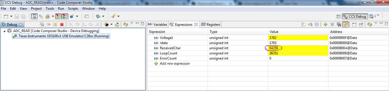
but using this code the data i am receiving via SCI is totally different from the sending data. I am sending the data in a variable called Voltage1 and receiving the data via SCI in a variable called ReceivedChar. But the value of this two variables are totally different. A screenshot of the "Watch Expression" window is attached below. Here i am keeping the Voltage1 constant ( value of Voltage1 is always around 1782).