This thread has been locked.
If you have a related question, please click the "Ask a related question" button in the top right corner. The newly created question will be automatically linked to this question.
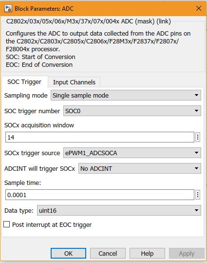
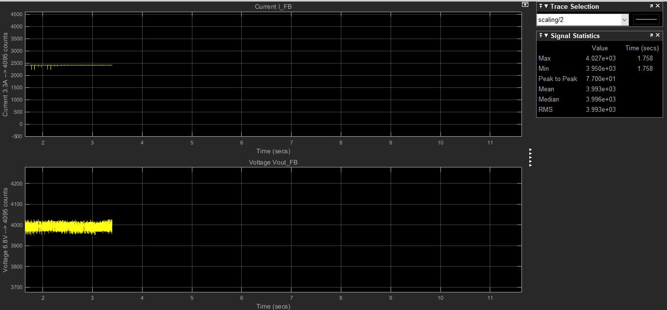
I configured the ADC using c2000 embedded coder support package and connected the A0 pin to the ground and the 3.3V pins in the launchpad. For both readings get a noise. Following image shows the reading when the A0 connected to the 3.3V pin. Why is that happening.
configuration parameters of ADC shown below. ePWM1 frequency is 20kHz. I changed the board, changed the power supply and nothing works.
Damith
Hi, I was dealing with this thing by hardware, I could recommend you to put a ferrite bead in series with the ADC input pin, also resolving by software substracting that kind of "offset" . Does the signal you have to measure is, at least, 100 times bigger than that noise, if yes then I could tell you not to worrie about, but if not, then you will have to make some sort of digital/filter in order to keep your measurement in a good shape
Mike
Damith
How are you measuring the mains? I could recommend you the AMC1200 or any of that family of The AMC or you can use the ISO 224 , in the AMCXXXX you have The output mounted with DC offset and you can put a comparator with hysteresis to avoid multiples Zero crossings
Regards
Mike
Damith,
I was re-reviewing the intial embedded coder GUI picture; can you comment/show the channel listing tab? There is an errata regarding the first sample of this ADC from any idle state; that is it will be corrupt.
There are two workarounds listed in the errata http://www.ti.com/lit/er/sprz292p/sprz292p.pdf
1)Double sample the first channel in a conversion sequence and discard the first sample result
2)Enabled the ADCNONOVERLAP bit as well as the ADCCLKDIV bit. This will slow down the ADC clock, but the first sample is usuable.
Let me know if this addresses the issue.
Matt