This thread has been locked.

If you have a related question, please click the "Ask a related question" button in the top right corner. The newly created question will be automatically linked to this question.

TMS320F280049: Crystal driving

Part Number: TMS320F280049
Other Parts Discussed in Thread: LMH6715

Hi

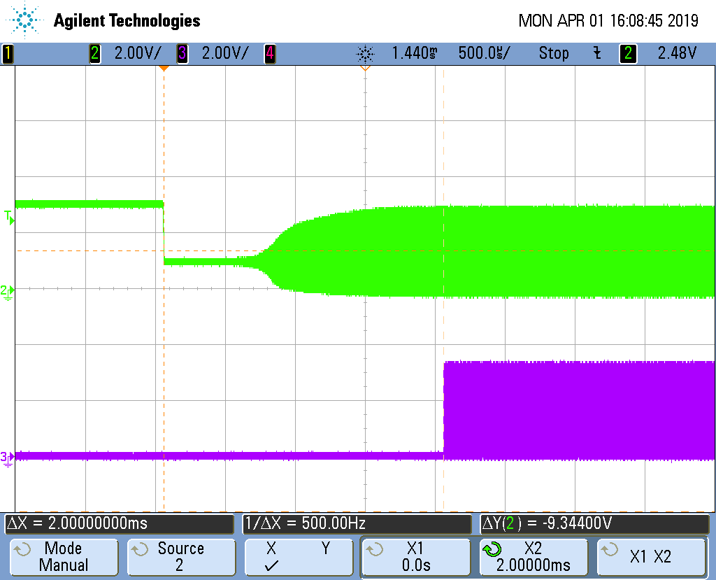
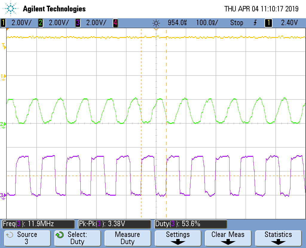
I have been measuring the crystal signals on the 28069  microcontroller board we use. The main thing is to make sure the crystal is not overdriven (or under driven) and has enough gain margin to reliably start given tolerances and temperature extremes. As we will be moving to the 280049 I thought I would measure the 280049 launchpad crystal oscillator. As I do not have an expensive current probe or FET voltage probe I built a unity gain wideband buffer amplifier with 2pF input capacitance. I measure 3.16Vpp (Peak to Peak) with of course a DC offset. This seems consistent with the spec for the 280049, whose oscillator voltage is more than the 1.8V specified for the 28069.

The ESC-200-18-30B crystal is specified for 20MHz 18pF 40ohm 100uW max.

If you use a formula quoted by ST in an Oscillator Design Guide from them, one can estimate the crystal drive power from the voltage.

Pd = Irms^2 * ESR

Irms = 2 pi F * Ct * Vpp/(2 *sqrt(2))

Ct = C1 + (Cstray/2) + Cprobe  = 15pF + ? + 2pF. Assuming about Cstray = 4pF (pin input capacitance + PCB capacitance)  then Ct = 19pF.

This then gives Pd = 2.66mA ^2  * 40  = 284uW and the crystal is specified for 100uW max.

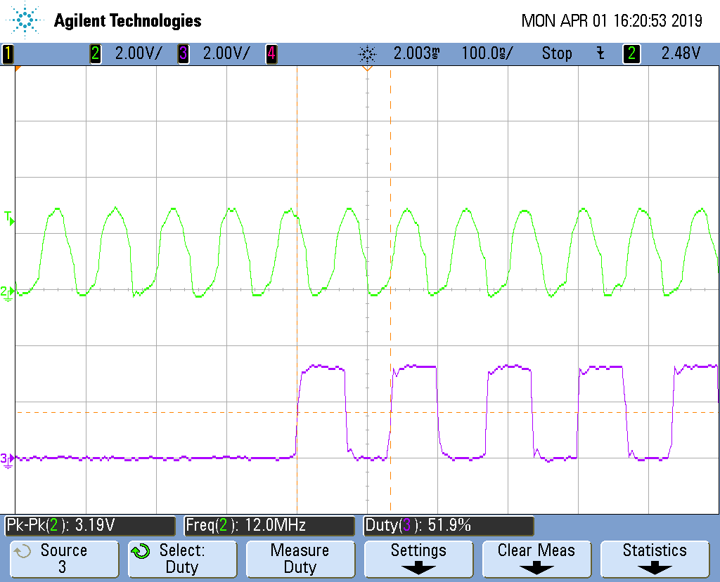
OK, its a development board and 40ohm is ESR max. So no big deal?! I have also had some pre-production boards with 200uW in a different 100uW max. crystal and no problems short term. However, the same crystal size from another manufacturer states Pd max as 300uW. I am not a crystal expert and do not know what the statistical difference between max. ESR and typical likely is. I also cannot vouch for the above formula, but I have used it and compared the result to a current measurement of a crystal at 12MHz (see later on the probe I used) and the results were comparable.

The point really is TI provides  little information in general on crystal oscillator design. The statement in the data-sheets is :

"TI recommends that the crystal manufacturer characterize the crystal with the application board" - not much help really.

There is no information for instance on the oscillator transconductance - a figure useful in calculating likely gain margins before embarking on measurements.  If you take the development board design then you may have problems later in the field - or maybe not.

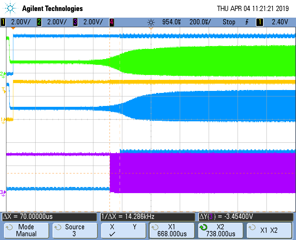
If you want to measure the current in the crystal without an expensive current probe I have also done the following to measure 10-12MHz crystals:

39turns on a 4C65 TN10/6/4 NiZn ferrite core terminated with 390ohms (10mV/mA). Pass some thin coax through the core as primary and connect in series with the crystal - all leads short as possible. Ground one end of the shield to the oscillator / micro ground. You then need 2 or more stages of wide bandwidth opamps with gain 3 - 4 each. I used two AD8039 amplifiers with gain each 4, but a current feedback type say LMH6715 may be better. Apply HF layout  see  Jim Williams'

www.analog.com/.../dn101f.pdf

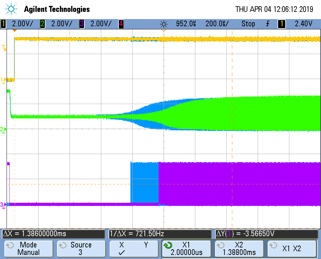
Output the amplifier though 50ohms and terminate with 50ohms on the scope. I calibrated the probe by measuring the current output of a Keysight function generator with its 50ohm output  shorted. Alternatively use a higher resistor value i.e., 1K and set to 2Vpp to get 2Vpp/1050ohms = 1.9mApp. Leads short as possible!

Finally, I know I make mistakes (believe me!) so don't accept what I have said as read - try to measure the crystal oscillator yourself and make your own conclusion. I hope in future TI will lend a bit more support to the topic.

Cheers

  • Hi Andrew,

    Thanks for providing the feedback. I would however like to clarify a few things. The aim of our documentation is to provide the essential information customers need to build their designs without cluttering it with complicated and arguably unnecessary information. All the information a customer needs to choose a quartz crystal for our crystal oscillator is provided in the datasheet.

    The transconductance is indirectly reflected in our ESR specification. As long as you meet our maximum ESR specification, you don't need to worry about the transconductance/gain not being enough to oscillate the crystal.

    The drive level is the maximum our crystal oscillator can drive the quartz crystal so you'll need to choose a quartz crystal which has a bigger drive level. Alternatively, you can use a damping resistor to reduce the crystal oscillator drive level. However, this doesn't come for free as that will increase the ESR of the circuit and possibly violate our ESR spec.

    The statement "TI recommends that the crystal manufacturer characterize the crystal with the application board" means that we have no control on how the board and or quartz crystal's characteristics will vary across all conditions. It's the customer's responsibility to make sure that the board and crystal variation across all conditions stays within our specification.

    We value your feedback. We plan on providing a step-by-step guide on choosing a quartz crystal for our crystal oscillator based on the information already provided in the datasheet in a future update. Let me know if there is anything that is not clear from my response.
  • Hi Andrew,

    Do you have anymore questions or concerns on this?

    I'm working with our design team to see if there is any possibility of reducing the 1mW specification. In the meantime, if you have trouble finding a crystal that meets our 1mW specification, you can check out https://www.ctscorp.com/wp-content/uploads/2015/11/008-0308-0.pdf . We have used a few of their crystals in our validation. According to their datasheet, their crystals can accept 1mW.

  • Update from the design team still pending.
  • Hi Frank

    Thanks for the feedback - and sorry for the delay getting back.

    I use a crystal from CTS a 445I23C12M00000 rated at 300µW max. It is a 12MHz 16pF ESRmax=50ohm. The exact same size Crystal package from Abracon is rated 100µW max. Why - I do not know. Of course 12MHz does not scale exactly to 200MHz internally.

    12MHz * (Imult + fmult/4) / 2 = 12 * 33.25 / 2 = 199.5MHz. Obviously, 10MHz or 16MHz would scale exact to 200MHz but I had trouble getting one (we are not a large company).

    The lower frequency crystal for the same load capacitance reduces the power dissipation even though the ESR of the crystal is a bit higher. We usually do not have a problem with frequency tolerance of crystals in our application so that is of secondary importance.

    I guess I wanted to demonstrate for those users where high reliability is required, do not take for granted the Evaluation Board designs, and to note that the crystal drive level of the 280049 and 28069 are different.

    It is good to hear that TI is looking into improving the guidlines in this respect.
  • Hi

    I just realized I described a 12MHz crystal that we used in a 28377d design we did. I got confused and stated 12MHz * (Imult + fmult/4) / 2 = 12 * 33.25 / 2 = 199.5MHz  - that was for the 28377d, and that PLL frequency would of course not be approprate for the 100MHz 280049. The given crystal data is correct however and I would consider using it in a 280049 design as well because the drive power will be a lot lower than that for the 20MHz one on the Evaluation Board. But I have not yet tried that crystal with the 280049.

    Andrew

  • Hi Andrew,

    Sorry about the late reply on this. I was tied up with another activity so wasn't able to close the loop on this. I'll attend to this next week and hopefully provide the final response so we can close this thread correctly answered.
  • Hi Frank

    Not in a hurry for the information. I can see on the forums that you are a very busy person - and the service TI provides here is in my opinion and I expect 99.5% of everyone else -  fantastic.

    Andrew

  • Hi Andrew,

    Thanks for the kind words, we appreciate that :-). I'll send the final resolution across when it's ready.
  • Hi Andrew,

    To close the discussion on this, after some additional experiments and discussions with our design team, the 1mW max drive level is fairly accurate and cannot be reduced. In addition, since we have no control over the characteristics of the quartz crystal a user uses, the onus is really on the user to characterize the chosen crystal with our oscillator to make sure it always powers up and that the crystal isn’t being over driven across all operating conditions.

    Nevertheless I have come to agree with your view point that we should provide more information in the datasheet. I have filed a documentation improvement request to update the datasheet to include guidance on how a user can choose a quartz crystal that will work with our oscillator and how they can make sure both oscillator requirements and quartz crystal requirements aren’t violated. This update will hopefully be in the next release of the F280049 datasheet and family of devices. Thanks for your patience.
  • Hi Frank

    OK, pleased to hear that, I look forward to receiving the updated datasheet in the future.

    We are starting the board design now and after doing a crystal survey have come to the conclusion we will probably have to use a metal can HC-49/US (S being the common SMD version of the ubiquitous HC-49U). Even some of them are spec'd to max 500uW, but you get 1mW. Basically, I cannot find any suitable crystal in resin or metal in a compact or low profile form.

    The closest I could find in a compact resin form was the earlier mentioned CTS445 with 300uW max rating and 50ohm, 85C, 12MHz, 12pF. For that I calculate about 179uW. The 12pF is still within the range quoted in the datasheet by TI (Table 5-20). I have made contact with CTS and are waiting a reply. I asked for a recommendation and whether they could provide more information on the max. ESR figures that get quoted to enable a risk assessment. It would be good if I could reliably use the smaller crystal size as it makes routing tracks in the area of the oscillator pins easier. I might try and get hold of a Tektronix CT-1 to measure the crystal current accurately to be on the safe side.

    Luckily in this design I think we can also use a larger crystal package. But it seems to me increasing the oscillator drive voltage on the 280049 has reduced the number of options for crystals. As I said earlier, the manufacturer's do not seem to release details other than the max ESR rating for the crystals so calculating the loss with that will often be over cautious, just as using a blank 1mW rating for the crystal will result in a crystal maybe 11.5 x 4.7 x 4.2 mm in size, compared to the 64pin DSP's 11.2 x 11.2mm.

    One final word,  Frank can you confirm then that the 20MHz crystal used on the 280049 launchpad does not then fulfil the 1mW recommendation. I think that is important, as many people look to that as a reference design and I am sure many just adopt the crystal circuit as given. I am certainly guilty of that as well in the past.

    Kind Regards

    Andrew Green

  • Hi

    I recalculated 179uW for a CTS445 with 300uW max rating and 50ohm, 85C, 12MHz, 12pF. The 12pF is still within the range quoted in the datasheet by TI (Table 5-20). I have made contact with CTS and are waiting a reply. I asked for a recommendation and whether they could provide more information on the max. ESR figures that get quoted to enable a risk assessment. It would be good if I could reliably use the smaller crystal size as it makes routing tracks in the area of the oscillator pins easier. I might try and get hold of a Tektronix CT-1 to measure the crystal current accurately to be on the safe side.

    Andrew
  • Andrew,

    I would recommend you use a damping resistor (Rd) in-series with X2 for your design if your measurement is showing that the crystal is being over-driven. How much damping you need will depend on the results of your crystal measurements and how much the crystal in question is being over-driven. The only hard requirement on our end is that the Rd + Crystal_ESR < Our_ESR_Max_Spec or else the crystal most likely won't start up.

    To accurately measure the crystal characteristics (motional inductance, capacitance, resistance.. etc), you will need a network analyzer. However, i believe you can estimate the ESR if you have a current probe. The reason for this is, when the crystal starts oscillating at it's fundamental, ESR = Rmotional. Since only the resistance is left, you should be able to use ohm's law at the crystal network to calculate the ESR using the rms current flowing through the crystal and the rms voltage delta between the crystal nodes. I think the only concern is, most current probes don't do well with the "small" currents and since the power calculation squares the current, any small error in the measurement is amplified.

    I wouldn't worry too much about the CL (within reason) because that mostly just pulls the frequency. In my opinion, the most important parameter is the ESR spec because if you exceed that, the crystal won't start-up and your system will limp.

    I understand your concern about the launchpad and i know most of our customers use that to pick components for their design. I haven't personally measured the driven level of the crystal on the F280049 launchpad but if i were to hazard a guess, i would say it's probably being over-driven. However on the launchpad, we have a placeholder resistor in series with X2. This is currently populated with 0ohms. I would be interested to hear your reply from CTS.
  • Hi Frank

    Thanks for your input  - I have found the discussion very useful.

    Yes, we always use a damping resistor, but I have not included its effect in the calculations I have made just yet.  One parameter that would help there is to know the output impedance of the oscillator. Then one could calculate its effect accurately before making measurements. In any case we do have a Network Analyser here. It is not a real high end type, but the Omicron Bode 100 gives in general very good results.

    CTS 445I23C12M00000  12MHz 16pF

    Co = 3.27pF

    Rm = 15.94ohm  (Motional Resistance)

    fs = 11.9987MHz

    fp = 12.006MHz

    Cs = 3.978fF

    Ls = 44.22mH

    ESR = Rm * (1 + Co/Cl)^2 = 23ohm,   for Cl = 16pF

    As expected this is less than the 50ohm maximum in the datasheet. The problem is that it is just one sample, and we do not know how the ESR varies  over the lifetime, only that it is less than the given maximum when driven correctly.

    If one applies the Drive Level Formula  (from TI SWRA495F) DL = ESR*(pi * f * (Cl + Cs) * Vpp)^2  that gives  91µWatt for Vpp 3.3V. But for how long? I can imagine for many users they could run with a 100µW max. crystal and never have a problem, depending on the product on time, market lifetime, and temperature.

    I think with either a 12pF calibrated crystal, or even a 16pF one loaded with just 12pF, I am well on the safe side with this CTS crystal as the DL is even lower. I will certainly report back what CTS says, but I am not holding my breath.

    I would add of course a 12MHz Crystal will not give a 100MHz SysClk only 99MHz (or is there a trick I am missing?). The nice thing about 12 to me seems that the product of ESRmax* f ^2 seems the lowest for some of the crystals I have seen. This reduces the DL.

    CTS 445:

    10 MHz - < 12 MHz,  ESRmax = 100 Ohms  ->  f^2*ESR = 100*100 = 10000

    12 MHz - < 16 MHz, ESRmax = 50 Ohms     ->  f^2*ESR = 144*50 = 7200

    16 MHz - < 30 MHz, ESRmax = 40 Ohms     ->  f^2*ESR = 256*40 = 10240

    Addendum 1:

    So I just made some measurements on the Launchpad with its 20MHz Crystal for different damping resistors (R31) and measured the following p-p voltages on the Pierce oscillator input pin X1 (C39), using the calibrated opamp-buffer described at the start of the post.

    Rd = 0  gave 3.21Vpp

    Rd = 220R gave 2.87Vpp

    Rd= 470R = 2.63Vpp

    Rd = 1K  = 2.25Vpp

    Rd = 1K5 = 2.0Vpp

    (all voltages above were scaled by 0.95 for bandwidth of measuring opamp at 20MHz)

    Clearly this reduced voltage will help as Frank pointed out. But what should be then tested is the start-up time and safety margin to ensure the oscillator always starts reliably. Normally this involves adding resistance in series with the crystal until it stops oscillating, then dividing this value by the ESRmax. Depending on which guideline you follow this should be a minimum of  3 - 10, with 5 being an often quoted figure. I would have done that but the crystal on the Launchpad is a bit difficult to remove.

    Addendum2:

    I managed to remove the 20MHz ECS Crystal from the 280049 Launchpad with a hot-air desoldering tool, and made the following measurements with a damping resistor Rd at the oscillator output and various values of Rx in series with the crystal to check the safety margin. In all cases oscillation was observed to occur. The oscillation start times were not recorded.

    ECS-200-18-30B-AGN-TR 20MHz 18pF

    Rx=0, Rd=220, Vpp at X1 = 2.76V

    Rx=0, Rd=1K, Vpp at X1 = 2.12V

    Rx=220, Rd=220, Vpp at X1 = 0.99V

    Rx=220, Rd=470, Vpp at X1 = 0.81V

    Rx=220, Rd=1K, Vpp at X1 = 0.54V

    (all voltages above were scaled by 0.95 for bandwidth of measuring opamp at 20MHz)

    CTS 445I23C12M00000  12MHz 16pF  (leaving  the two 15pF load capacitors in the 280049 Launchpad unchanged)

    Rx=0, Rd=220, Vpp at X1 = 3.09V

    Rx=220, Rd=220, Vpp at X1 = 1.75V

    Rx=220, Rd=470, Vpp at X1 = 1.64V

    Rx=470, Rd=470, Vpp at X1 = 1.04V

    (all voltages above were scaled by 0.97 for bandwidth of measuring opamp at 12MHz)

    Kind Regards

    Andrew Green

  • Hi Andrew,

    Thanks for providing the measurements you took. This has definitely been a fruitful discussion. Seems like you have a good handle on things. I don't have the oscillator output impedance off-hand and will have to contact our design team. We don't have a network analyzer at our local site at the moment but I'll try and source one.

    Your results on Rd measurements is very interesting. I would however caution against having the pk-pk voltage on X1 drop too low. Without revealing too much about the design, i can tell you that there is an internal comparator somewhere in the circuit that monitors the voltage on X1. If this pk-pk voltage drops too low, the comparator will stop recognizing it and there will be no clock to the device. Also even though we don't specify negative resistance directly, i can tell you for a fact that oscillation at 10MHz has the biggest negative resistance so you have more leeway in how much Rd you can use.

    Since you are this far into the crystal analysis, i would recommend you throw in start-up times as well. If you want any suggestion on how to accurately measure this, one of the approaches we have used is to measure the duty cycle of the clock over time. CLKSRCCTL3 register will directly bring out XTAL on a GPIO. Note that this clock will be a square wave and not a sine wave as the signal on X1. So then the start-up time of the crystal will be the delta time between when XOSCOFF bit is written to when the duty cycle on XCLKOUT gets to within 45% to 55%. If you ran this experiment, you will notice that the start-up time of the crystal gets significantly longer as Rd is increased to the point where it doesn't start-up anymore as you correctly pointed out. You will need to use some form of frequency/period analysis toolkit since it requires plotting the duty cycle of every period from time 0. You will also find out that 10MHz has the slowest start-up time because it takes longer for the 10MHz signal to complete the feedback loop.

    I don't think you can get 100MHz exactly with 12MHz crystal. It seems to me that all the multiplier and divider combinations that will give you 100MHz violate the frequency ranges we have specified in the datasheet.

    I'm working with another co-worker to send a few of our boards to our supplies for drive-level measurements. In all honesty, the crystal manufacturers are the experts and best qualified to make these measurements accurately. I don't have a timeline for this and can't promise any dates but we will definitely look into this a lot closely.
  • Hi Frank

    Thanks for the tip about measuring the start-up time and the comparator - I will definitely look into it. I got burnt a bit with the 28069 with start-up time.I had Rd=470ohms and adjusted the oscillator startup wait delay in my test code, but then forget to tell the software guys. Some boards they were developing the "real" code on started within the TI library defined time, and others did not. But we resolved it quickly enough and before we were in production.

    Just measured the following on the Launchpad Crystal ECS-200-18-30B-AGN-TR (ESR max = 40, Cload = 18pF, DLmax = 100uW) using our Bode 100

    Rm = 9.83ohms

    Cp = 3.25pF

    fs = 19.997MHz

    fp = 20.024MHz

    Cs = 8.77fF

    Ls = 7.22mH

    ESR (with Cload = 18pF) = Rm*(1+Co/Cl)^2 = 13.7ohm

    ESR (with Cload = 12pF) = Rm*(1+Co/Cl)^2 = 15.8ohm

    So in this case the ESR is much less than the 40ohm maximum in the datasheet, so the crystal on the Launchpad is probably being driven close to the specified 100uW maximum, but maybe not over it. But at the risk of sounding repetitive that's the problem we have as designers - the crystal manufacturers only provide the maximum value and no statistics. But with a judicial choice of Rd, I think there are solutions available without resorting to a 1mW Crystal.

    Addendum 1:

    I used the CTS 12MHz Crystal with Rd=470ohm and routed XCLKOUT to  GIPO16 as per your suggestion. After connecting the 5V power to the Launchpad you see that X2 goes high, and a few msec later it drops sharply to about 1V, then after about 500usec the oscillation starts to build up. I triggered a one-shot on this falling edge. I have attached two scope captures. Green Trace = X2, Purple Trace= GPIO16.

    From the green X2 falling transition to 1V until the start of XCLKOUT appearing on GPIO16 is 2msec. Can I assume that is the oscillator startup delay needed, or is it actually longer than that still, and I have to use the "Register" method  you described. The purple trace reaches 51% duty almost immediately it starts, as seen in the zoomed in second attachment.

    I also added 200ohm in series with the crystal to verify if a safety margin of "about" 5 for worst case ESR was there. There was no difference in the waveforms to speak of, and the 2msec delay until XCLKOUT appeared remained the same. Leaving Rx=200R in, and changing Rd to 1K or 0ohm surprisingly  also had no effect - the 2msec remained the same.

    Addendum 2:

    I would add that the violet XCLKOUT trace is configured as PLLSYSCLK. It happened to be the PLL was set to 5 and the XCLKOUT divider  to 8 so the frequency = 12MHz x 5/8 = 7.5MHz.

    Cheers

    Andrew


  • Hi Andrew,

    The scope shot you provided is a familiar sight :-). However, it doesn't look like you are measuring the crystal startup time but rather the PLL startup time through INTOSC2 or possibly some combination I'm not quite sure of yet. I believe this is one of the reasons you aren't seeing the startup time change with varying Rd. To accurately measure it, you will need to bring out XCLKOUT itself using CLKSRCCTL3.XCLKOUTSEL = 7 and then turn the crystal on/off with XTALCR.OSCOFF. To indicate when OSCOFF was written, you can wrap that register write with a GPIO toggle and monitor the GPIO toggle also on the scope.

    It's also interesting you saw the duty cycle hit approximately 50% right away. If you think about the power up time of any module, not just a crystal, they all have a similar characteristic. This characteristic is: fast or slow slew followed by some overshoot/undershoot then eventual settling. Interpreting this for the crystal, you should expect to see some of these characteristics. In essence, for it to hit 50% duty cycle right away is a bit abnormal. What i would expect to see is a duty cycle that bounces around a few times from 0% to 100% before eventually settling to 45% to 55% and staying there. This is one of the reasons why you would need to do a cycle-by-cycle plot of the duty cycle to see when the XCLKOUT duty cycle enters the 45% to 55% window and stays there. This is a accurate however a bit tedious method.

    I understand your reasoning for wanting more than just the max spec because it's good for design analysis. However, a design is more robust if it's designed against the max spec especially if one is given. This is one advice we give to our users to always design as close to the max specification as they can because even though most devices they receive won't be anywhere close to the max spec, it's possibly to receive a device that hugs the max spec. I think this applies everywhere in the industry.

    As you alluded to, our recommendation in the datasheet will be along the lines of the user using Rd but testing the various crystal facets to make sure the chosen Rd is sufficient across and conditions.
  • Hi Frank

    OK, I have some results that seem to make better sense. This is what we did:

    Setup that XCLKOUTso that it could be viewed and this time was configured to OSCCLK. Then in the SysXtalOscSel() Routine in (f28004x_sysctrl.c) where the Crystal oscillator is activated we toggled a gpio pin as suggested by you. The following results are for the CTS 12MHz Crystal with Rx=200ohms in series with crystal to simulate a "worst" case condition. I actually forgot to take it out,  made the measurements and thought oh what the heck. I made measurements for Rd = 0, 470R, 1K. Trying to find the 45-55% duty point is very subjective but you can see the influence of Rd. I have attached four scope captures. In the following one the blue curves were saved for Rd=470, and the Y/G/V are for Rd=0ohms. Y =  GPIO toggled after oscillator is enabled, G = Oscillator X1 input, V = OSCCLK output on GPIO16.  Notice I shifted the saved blue waveforms around for better viewing. I measured for 0ohms 900usec to reach 45-55%, and for 470ohm 960usec.

    In the following two captures you see 1) how OSCCLK does not start with 50% duty (as you foresaw) and later when it does reach the target range.

    The last capture below shows the case for Rd=470 (saved in blue) compared to Rd=1K in Y/G/V. For Rd=1K I measured a time of 1380usec.

    So it confirms that increasing/adding a damping resistor does increase the start-up time needed, but it is not necessarily much longer. Also even with 200ohms added in series with crystal and Rd = 1K the oscillator started.

    Frank, I think we should close this issue now (it was very interesting,  but I have spent much too much time on it). I am happy that I have a solution that seems to meet Crystal Drive Level requirements and Oscillator Safety Margins, and in a footprint that is not too big. Still no reply from CTS. If someone else decides to use a crystal from CTS, or decides the crystal on the launchpad fulfils their requirements, then in both cases the responsibility lies with them. As it stands I will be using something that is still outside the 1mW specification in the TI datasheet. It is my responsibilty to ensure it works.

    Kind Regards

    Andrew Green

  • Hi Frank

    OK, I have some results that seem to make better sense. This is what we did:

    Setup that XCLKOUTso that it could be viewed and this time was configured to OSCCLK. Then in the SysXtalOscSel() Routine in (f28004x_sysctrl.c) where the Crystal oscillator is activated we toggled a gpio pin as suggested by you. The following results are for the CTS 12MHz Crystal with Rx=200ohms in series with crystal to simulate a "worst" case condition. I actually forgot to take it out,  made the measurements and thought oh what the heck. I made measurements for Rd = 0, 470R, 1K. Trying to find the 45-55% duty point is very subjective but you can see the influence of Rd. I have attached four scope captures. In the following one the blue curves were saved for Rd=470, and the Y/G/V are for Rd=0ohms. Y =  GPIO toggled after oscillator is enabled, G = Oscillator X1 input, V = OSCCLK output on GPIO16.  Notice I shifted the saved blue waveforms around for better viewing. I measured for 0ohms 900usec to reach 45-55%, and for 470ohm 960usec.

    In the following two captures you see 1) how OSCCLK does not start with 50% duty (as you foresaw) and later when it does reach the target range.

    The last capture below shows the case for Rd=470 (saved in blue) compared to Rd=1K in Y/G/V. For Rd=1K I measured a time of 1380usec.

    So it confirms that increasing/adding a damping resistor does increase the start-up time needed, but it is not necessarily much longer. Also even with 200ohms added in series with crystal and Rd = 1K the oscillator started.

    Frank, I think we should close this issue now (it was very interesting,  but I have spent much too much time on it). I am happy that I have a solution that seems to meet Crystal Drive Level requirements and Oscillator Safety Margins, and in a footprint that is not too big. Still no reply from CTS. If someone else decides to use a crystal from CTS, or decides the crystal on the launchpad fulfils their requirements, then in both cases the responsibility lies with them. As it stands I will be using something that is still outside the 1mW specification in the TI datasheet. It is my responsibility to ensure it works.

    Kind Regards

    Andrew Green

  • Hi Andrew,

    I'm glad to see your last result is more inline with expectation. This was definitely a fruitful discussion. It seems you have a very good understanding of everything now. We will take lessons learned from it and incorporate into updates for our documentation.

    If you ever come back to this in the future, keep in mind that you don't need to set OSCCLK to XTAL to measure it. You can ran OSCCLK off INTOSC as usual and just enable XTAL on XCLKOUT. Last thing is the 45% to 55% requirement is not arbitrary, it's our duty cycle spec.

    I'll go ahead and close this post. If you ran into any future issues, be sure to let us know. Best of luck on your project.