Part Number: TMS320F28335
Tool/software: Code Composer Studio
Dear Sir/Madam,
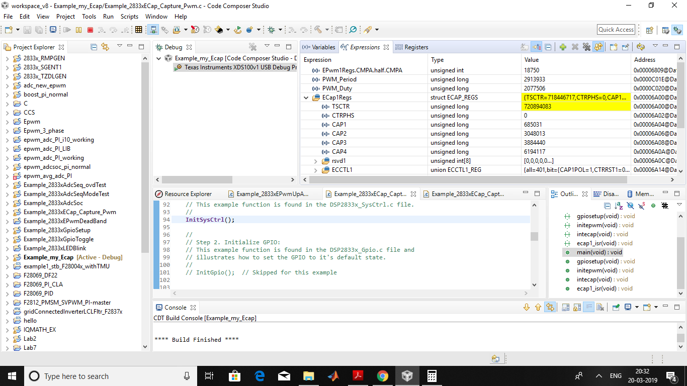
I want to capture the PWM signal from EPWM with ECap feature. I have generated a 1kHz signal from EPWM1A and I gave to the ECAP1 from pin 24. But the capture registers are always empty. The ISR is not executing. Please help me in this regard. Please find the code attached.
//###########################################################################
//
// FILE:   Example_2833xECap_Capture_Pwm.c
//
// TITLE:  eCap capture PWM Example
//
//! \addtogroup f2833x_example_list
//! <h1> eCap capture PWM (ecap_capture_pwm)</h1>
//!
//! This example configures ePWM3A for:
//! - Up count
//! - Period starts at 2 and goes up to 1000
//! - Toggle output on PRD
//!
//! eCAP1 is configured to capture the time between rising
//! and falling edge of the ePWM3A output.
//!
//! \b External \b Connections \n
//! - eCap1 is on GPIO24
//! - ePWM3A is on GPIO4
//! - Connect GPIO4 to GPIO24.
//!
//! \b Watch \b Variables \n
//! - ECap1IntCount - Successful captures
//! - ECap1PassCount - Interrupt counts
//
//###########################################################################
// $TI Release: F2833x Support Library v2.00.00.00 $
// $Release Date: Thu Oct 18 15:47:35 CDT 2018 $
// $Copyright:
// Copyright (C) 2009-2018 Texas Instruments Incorporated - http://www.ti.com/
//
// Redistribution and use in source and binary forms, with or without
// modification, are permitted provided that the following conditions
// are met:
//
//   Redistributions of source code must retain the above copyright
//   notice, this list of conditions and the following disclaimer.
//
//   Redistributions in binary form must reproduce the above copyright
//   notice, this list of conditions and the following disclaimer in the
//   documentation and/or other materials provided with the
//   distribution.
//
//   Neither the name of Texas Instruments Incorporated nor the names of
//   its contributors may be used to endorse or promote products derived
//   from this software without specific prior written permission.
//
// THIS SOFTWARE IS PROVIDED BY THE COPYRIGHT HOLDERS AND CONTRIBUTORS
// "AS IS" AND ANY EXPRESS OR IMPLIED WARRANTIES, INCLUDING, BUT NOT
// LIMITED TO, THE IMPLIED WARRANTIES OF MERCHANTABILITY AND FITNESS FOR
// A PARTICULAR PURPOSE ARE DISCLAIMED. IN NO EVENT SHALL THE COPYRIGHT
// OWNER OR CONTRIBUTORS BE LIABLE FOR ANY DIRECT, INDIRECT, INCIDENTAL,
// SPECIAL, EXEMPLARY, OR CONSEQUENTIAL DAMAGES (INCLUDING, BUT NOT
// LIMITED TO, PROCUREMENT OF SUBSTITUTE GOODS OR SERVICES; LOSS OF USE,
// DATA, OR PROFITS; OR BUSINESS INTERRUPTION) HOWEVER CAUSED AND ON ANY
// THEORY OF LIABILITY, WHETHER IN CONTRACT, STRICT LIABILITY, OR TORT
// (INCLUDING NEGLIGENCE OR OTHERWISE) ARISING IN ANY WAY OUT OF THE USE
// OF THIS SOFTWARE, EVEN IF ADVISED OF THE POSSIBILITY OF SUCH DAMAGE.
// $
//###########################################################################

//
// Included Files
//
#include "DSP28x_Project.h"     // Device Headerfile and Examples Include File


Uint32 PWM_Period;
Uint32 PWM_Duty;
//
// Defines to configure the start/end period for the timer
//
void gpiosetup(void);
void initepwm(void);
void intecap(void);

//
// Function Prototypes
//
__interrupt void ecap1_isr(void);


//
// Main
//
void main(void)
{

    InitSysCtrl();
    DINT;
    InitPieCtrl();
    IER = 0x0000;
    IFR = 0x0000;
    InitPieVectTable();
    gpiosetup();
    initepwm();
    intecap();
    EALLOW;         // This is needed to write to EALLOW protected registers
    PieVectTable.ECAP1_INT = &ecap1_isr;
    EDIS;      // This is needed to disable write to EALLOW protected registers
    IER |= M_INT4;
    PieCtrlRegs.PIEIER4.bit.INTx1 = 1;
    EINT;           // Enable Global interrupt INTM
    ERTM;           // Enable Global realtime interrupt DBGM
    for(;;)
    {
        __asm("          NOP");
    }
}

//
// InitEPwmTimer -
//
void gpiosetup(void){
    EALLOW;
    GpioCtrlRegs.GPADIR.bit.GPIO0=1;
    GpioCtrlRegs.GPAMUX1.bit.GPIO0=1;
    GpioCtrlRegs.GPAPUD.bit.GPIO0=0;
    GpioCtrlRegs.GPADIR.bit.GPIO24=0;
    GpioCtrlRegs.GPAMUX2.bit.GPIO24=1;
    GpioCtrlRegs.GPAPUD.bit.GPIO24=1;
    EDIS;
}
void initepwm(void){
    EPwm1Regs.TBCTL.bit.CTRMODE = 2; // Count up down
    EPwm1Regs.TBPRD = 37500;       // Set timer period
    EPwm1Regs.TBCTL.bit.PHSEN = TB_DISABLE;    // Disable phase loading
    EPwm1Regs.TBPHS.half.TBPHS = 0x0000;       // Phase is 0
    EPwm1Regs.TBCTR = 0x0000;                  // Clear counter
    EPwm1Regs.TBCTL.bit.HSPCLKDIV = 001;   // Clock ratio to SYSCLKOUT
    EPwm1Regs.TBCTL.bit.CLKDIV = 000;
    EPwm1Regs.TBCTL.bit.SYNCOSEL=1;
    EPwm1Regs.CMPA.half.CMPA =18750;    // Set compare A value
    EPwm1Regs.CMPB = 18750;              // Set Compare B value
    EPwm1Regs.DBCTL.bit.OUT_MODE=3;
    EPwm1Regs.DBCTL.bit.POLSEL=2;
    EPwm1Regs.DBCTL.bit.IN_MODE=0;
    EPwm1Regs.DBRED=200;
    EPwm1Regs.DBFED=200;
    EPwm1Regs.AQCTLA.bit.CAU=2;    // Set PWM1A on Zero
    EPwm1Regs.AQCTLA.bit.CAD=1;
    EPwm1Regs.AQCTLB.bit.CBU=2;
    EPwm1Regs.AQCTLB.bit.CBD=1;
}
void intecap(void){
    ECap1Regs.ECEINT.all = 0x0000;          // Disable all capture interrupts
    ECap1Regs.ECCLR.all = 0xFFFF;           // Clear all CAP interrupt flags
    ECap1Regs.ECCTL1.bit.CAPLDEN = 0;       // Disable CAP1-CAP4 register loads
    ECap1Regs.ECCTL2.bit.TSCTRSTOP = 0;     // Make sure the counter is stopped

    ECap1Regs.ECCTL2.bit.CONT_ONESHT=0;
    ECap1Regs.ECCTL2.bit.STOP_WRAP=3;
    ECap1Regs.ECCTL2.bit.REARM=0;
    ECap1Regs.ECCTL2.bit.TSCTRSTOP=1;
    ECap1Regs.ECCTL2.bit.SYNCI_EN=0;
    ECap1Regs.ECCTL2.bit.CAP_APWM=0;
    ECap1Regs.ECCTL2.bit.SYNCO_SEL=1;
    ECap1Regs.ECCTL1.bit.FREE_SOFT=0;
    ECap1Regs.ECCTL1.bit.PRESCALE=0;
    ECap1Regs.ECCTL1.bit.CAPLDEN=1;
    ECap1Regs.ECCTL1.bit.CAP1POL=1;
    ECap1Regs.ECCTL1.bit.CAP2POL=0;
    ECap1Regs.ECCTL1.bit.CAP3POL=1;
    ECap1Regs.ECCTL1.bit.CAP4POL=0;
    ECap1Regs.ECCTL1.bit.CTRRST4=1;
    ECap1Regs.ECEINT.bit.CEVT3=1;

}
__interrupt void ecap1_isr(void)
{
    ECap1Regs.ECCLR.bit.INT=1;
    ECap1Regs.ECCLR.bit.CEVT3=1;
    PWM_Duty = (int32) ECap1Regs.CAP2 - (int32) ECap1Regs.CAP1;
    PWM_Period = (int32) ECap1Regs.CAP3 - (int32) ECap1Regs.CAP1;
    //
    // Acknowledge this interrupt to receive more interrupts from group 4
    //
    PieCtrlRegs.PIEACK.all = PIEACK_GROUP4;
}