This thread has been locked.
If you have a related question, please click the "Ask a related question" button in the top right corner. The newly created question will be automatically linked to this question.
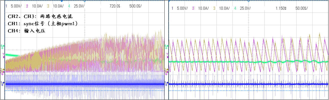
Customer reported an issue, that using eCAP to capture the period of an EPWM, the capture results showed lots of noise effect, but they were using the Output X-BAR to select the EXTSYNCOUT as the input signal for eCAP. Basically, it should be an internal signal capture, and it should not be affected by the external noise, but it did not help either.
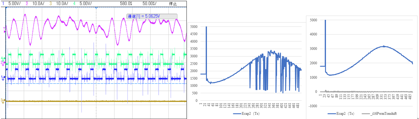
The previous results by capturing the EPWM output as below, which showed the capture results was affected by the noise. The right one should be the expected result.
The below settings select OutputXbar7 as the input for ecap2, and enable EPWM1SYNCOUT as the EXTSYNCOUT, which was muxed for OutputXbar7 .
ECap2Regs.ECCTL0.bit.INPUTSEL = 0x1E; //OUTPUT7-ECAP refers to 30 OutputXbarRegs.OUTPUT7MUX0TO15CFG.bit.MUX14 = 3; // SYNCOUT->OutputXbar7 OutputXbarRegs.OUTPUT7MUXENABLE.bit.MUX14 = 1; //1:enable 0:disable SyncSocRegs.SYNCSELECT.bit.SYNCOUT = 0;
The other settings for ECAP2 are as below.
ECap2Regs.ECEINT.all = 0x0000; // Disable all capture __interrupts ECap2Regs.ECCLR.all = 0xFFFF; // Clear all CAP __interrupt flags ECap2Regs.ECCTL1.bit.CAPLDEN = EC_DISABLE; // Disable CAP1-CAP4 register loads ECap2Regs.ECCTL2.bit.TSCTRSTOP = EC_FREEZE; // Make sure the counter is stopped ECap2Regs.CTRPHS = 0;//YQH test ECap2Regs.ECCTL1.bit.PRESCALE = EC_DIV1; // every time trig //0h (R/W) = Operate in continuous mode //1h (R/W) = Operate in one-Shot mode ECap2Regs.ECCTL2.bit.CONT_ONESHT = EC_CONTINUOUS; ECap2Regs.ECCTL2.bit.STOP_WRAP = EC_EVENT1; // WRAP after Caputure Event1 ECap2Regs.ECCTL1.bit.CAP1POL = EC_RISING; // Rising edge ECap2Regs.ECCTL1.bit.CTRRST1 = EC_DELTA_MODE; // Reset counter after latch //ECap2Regs.ECCTL1.bit.CTRRST2 = EC_ABS_MODE; // Do not reset counter after //ECap2Regs.ECCTL1.bit.CTRRST3 = EC_DELTA_MODE; // Reset counter after latch ECap2Regs.ECCTL2.bit.SYNCI_EN = EC_SYNCI_DISABLE; // Disable sync in //ECap2Regs.ECCTL2.bit.SYNCI_EN = EC_SYNCI_ENABLE; // Enable sync in //YQH test // 0h (R/W) = Disable sync-in option // 1h (R/W) = Enable counter (TSCTR) to be loaded from CTRPHS // register upon either a SYNCI signal or a S/W force event. ECap2Regs.ECCTL2.bit.SYNCO_SEL = EC_SYNCO_DIS; // Pass through ECap2Regs.ECCTL2.bit.CAP_APWM = EC_CAP_MODE; ECap2Regs.ECCTL2.bit.TSCTRSTOP = EC_RUN; // Start Counter ECap2Regs.ECCTL2.bit.REARM = EC_ENABLE; // arm one-shot ECap2Regs.ECCTL1.bit.CAPLDEN = EC_ENABLE; // Enable CAP1-CAP4 register loads
Could you please help check the reasons?
Hi Aki,
Can you label the plots you attached? I'm not sure what I'm looking at.
Frank,
For 1st image, CH1/CH4 are the EPWM1A/1B, CH2 need to confirm.
For 2nd image, it refers to the captured results for the period of EPWM1.
For 3rd image, it refers to the expected results for the period, or during light load(less noise).
Aki,
Ok. Can they bring out EXTSYNCOUT on a GPIO so we can see what it looks like for the problem case?
Frank,
Yes, they also brought out EXTSYNCOUT to GPIO11 with Output X-BAR 7.
CH1/2 are the inductor currents, CH4 is the EXTSYNCOUT at GPIO11.
As shown, the red highlighted ones should be the correct sync event, but the other spikes should be the system noise. Based on our understanding, these spikes should not affect the internal output XBAR signal to the ecap.
Sorry for the typo. CH2/3 are the inductor currents, CH1 is the EXTSYNCOUT at GPIO11.
Aki,
Looks like the eCAP is working correctly as it's capturing what is happening on that signal. Have you verified in the code to make sure no other signal is enabled unto Output X-BAR7?
Frank,
That is the key point we are confused with, that the EXTSYNCOUT should be an internal signal, which was sent to the ecap through internal output Xbar, so it should not be affected by the external noise. I will further check with them whether there are any other signals defined for Output X-BAR7.
Frank,
Customer double checked the result, and it was correct actually with the present method. However, they also need to capture the other channel EPWM3A's period, and they could not use the same method here since there is only one sync out signal. Could you please help check any suggestion for them? Thank you.
Aki,
This is not expected. It looks to me the ePWM output switching is coupling into the device. You can see in your first scope shot in the thread that the ePWM output has a lot of voltage spikes. Can they run the same experiment but not enable the ePWM output on the GPIO? i.e keep the test case the same. The only difference should be the GPIO mux option is not set to EPWM1A/B.
Frank,
Sorry i did not make it clear. The results at the beginning were from their previous method by capturing the EPWM1A output at the IO pin. Now, by using the internal EXTSYNCOUT as the ecap input, the results were as expected, from today's update. The remaining question is how to capture another epwm channel(EPWM3A).
Aki,
That is what I'm saying. My suspicion is the spikes on EPWM1A/B are coupling into the device and affecting EXTSYNCOUT even though they are not measuring EPWM1A/B. This is why I asked to try the experiment again with essentially no signal being brought out on a GPIO so we can see if that is what is causing this.
Aki,
Is it possible for them to clean-up the noisy EPWM output on their hardware?
Frank,
The noise is easily to coupled to pwm outputs especially during higher load. I think it should be considered if we can add filter module for the ecap. However, in the other hand, the minimum of the capture input pulse width in the datasheet is 20ns, and I assumed the noise spikes did not last for such time, but it seems that it did affect here.
Aki,
A coworker suggested using the GPIO synchronization which is essentially the filtering you are looking for. Have they already tried that? It will delay the signal a little bit but for the period measurement, I think that should be ok. In the future when they are designing their board, they need to make sure signals with fast edges like the GPIO are properly terminated so they don't see the ESL spikes. Let us know if the synchronization works.
Frank,
Thank you for the suggestion. It seems that GPIO synchronization can be also used even when it is defined as epwm output. I will check with customer for this option.