


Part Number: TMS320F28069
Other Parts Discussed in Thread: MOTORWARE, LAUNCHXL-F28069M, CONTROLSUITE
Hi guys,
I have a SIEMENS TAPAS community inverter which uses TMS320F28069 MCU. I want to establish SCI/UART between my PC and this board. The board (as shown in Fig. 1 below) does not have the UART to USB populated and I have used a USB to UART TTL (Fig. 2) for this purpose. Also, it required me to populate 4 Resistors (RC0402JR-070RL) for RX, TX lines as given in their schematic but I used a wire instead.
Figure 1

Figure2

In motorware, SCI is not included by default. Therefore, I have the following inclusions in
1) hal_obj.h
  SCI_Handle    sciAHandle;       //!< the SCI handle
  SCI_Handle    sciBHandle;       //!< the SCI handle
2) hal.c
in HAL_Handle HAL_init()
   // initialize the SCI handles

  obj->sciAHandle = SCI_init((void *)SCIA_BASE_ADDR,sizeof(SCI_Obj));
  obj->sciBHandle = SCI_init((void *)SCIB_BASE_ADDR,sizeof(SCI_Obj));
in HAL_setParams()

  // setup the sciA
  HAL_setupSciA(handle);
  // setup the sciB
  HAL_setupSciB(handle);
in HAL_setupGpios()

 // Setup your GPIOs for SCI
      GPIO_setPullup(obj->gpioHandle, GPIO_Number_28, GPIO_Pullup_Enable);
      GPIO_setPullup(obj->gpioHandle, GPIO_Number_29, GPIO_Pullup_Enable);

      GPIO_setQualification(obj->gpioHandle, GPIO_Number_28, GPIO_Qual_ASync);

      GPIO_setMode(obj->gpioHandle, GPIO_Number_28, GPIO_28_Mode_SCIRXDA);
      GPIO_setMode(obj->gpioHandle, GPIO_Number_29, GPIO_29_Mode_SCITXDA);
No changes for SCIB, as it set by default in motorware.
in HAL_setupPeripheralClks()

CLK_enableSciaClock(obj->clkHandle);
Clock for SCIB is enabled by default. Setup of the SCIA, SCIB modules is given below.
void HAL_setupSciA(HAL_Handle handle)
{
HAL_Obj *obj = (HAL_Obj *)handle;
SCI_reset(obj->sciAHandle);
SCI_enableTx(obj->sciAHandle);
SCI_enableRx(obj->sciAHandle);
SCI_disableParity(obj->sciAHandle);
SCI_setNumStopBits(obj->sciAHandle,SCI_NumStopBits_One);
SCI_setCharLength(obj->sciAHandle,SCI_CharLength_8_Bits);
// set baud rate to 115200
SCI_setBaudRate(obj->sciAHandle,SCI_BaudRate_115_2_kBaud);
SCI_setPriority(obj->sciAHandle,SCI_Priority_FreeRun);
SCI_enable(obj->sciAHandle);
return;
// end of HAL_setupSciA() function
}

void HAL_setupSciB(HAL_Handle handle)
{
HAL_Obj *obj = (HAL_Obj *)handle;
SCI_reset(obj->sciBHandle);
SCI_enableTx(obj->sciBHandle);
SCI_enableRx(obj->sciBHandle);
SCI_disableParity(obj->sciBHandle);
SCI_setNumStopBits(obj->sciBHandle,SCI_NumStopBits_One);
SCI_setCharLength(obj->sciBHandle,SCI_CharLength_8_Bits);
// set baud rate to 115200
SCI_setBaudRate(obj->sciBHandle,SCI_BaudRate_115_2_kBaud);
SCI_setPriority(obj->sciBHandle,SCI_Priority_FreeRun);
SCI_enable(obj->sciBHandle);
return;
// end of HAL_setupSciB() function
3) hal.h
//! \brief Sets up the sciA peripheral
//! \param[in] handle The hardware abstraction layer (HAL) handle
extern void HAL_setupSciA(HAL_Handle handle);


//! \brief Sets up the sciB peripheral
//! \param[in] handle The hardware abstraction layer (HAL) handle
extern void HAL_setupSciB(HAL_Handle handle);
4) proj_lab01.c
LED blink frequency is set to 1 Hz.
in main()
uint16_t dataRx;
uint16_t success;

  // For ever loop
  while(true)
  {
	  //Random numbers (3,4,255,0) transmit in main(), uncommented when Echoback is commented
/*	  dataRx=3;
	  SCI_putDataNonBlocking(halHandle->sciBHandle, dataRx);
	  dataRx=4;
	  SCI_putDataNonBlocking(halHandle->sciBHandle, dataRx);
	  dataRx=255;
	  SCI_putDataNonBlocking(halHandle->sciBHandle, dataRx);
	  dataRx=0;
	  SCI_putDataNonBlocking(halHandle->sciBHandle, dataRx);*/

	  //Echoback
	  if(SCI_rxDataReady(halHandle->sciBHandle))
	  {
	  while(SCI_rxDataReady(halHandle->sciBHandle) == 0);
	  dataRx = SCI_getDataNonBlocking(halHandle->sciBHandle, &success);
	  success = SCI_putDataNonBlocking(halHandle->sciBHandle, dataRx);
	  }
  }
in mainISR()
//uint16_t dataRx;
  // toggle status LED and random numbers (3,4,255,0) transmit in ISR() @ 1Hz
  if(gLEDcnt++ > (uint_least32_t)(USER_ISR_FREQ_Hz / LED_BLINK_FREQ_Hz))
  {
    HAL_toggleLed(halHandle,(GPIO_Number_e)HAL_Gpio_LED2);
    gLEDcnt = 0;

    //Uncommented when data not transmitted through main()

/*   dataRx=3;
   SCI_putDataNonBlocking(halHandle->sciBHandle, dataRx);
   dataRx=4;
   SCI_putDataNonBlocking(halHandle->sciBHandle, dataRx);
   dataRx=255;
   SCI_putDataNonBlocking(halHandle->sciBHandle, dataRx);
   dataRx=0;
   SCI_putDataNonBlocking(halHandle->sciBHandle, dataRx);*/
  }
All the remaining code lines remain unchanged.
Results of these codes:
Echoback
Only certain characters echoback (w,W,u,U,o,k,m,[,],{,}). This is done using Simulink and as well as in terminal available in code composer (CCSv6).
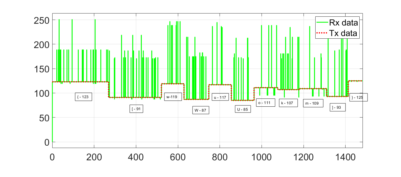
When I transmit any other characters apart from this it does not echo back correctly. Furthermore, after two characters other than the list it stops echoing.
Transmit in main()
When I transmit the values 3,4,255,0 continuously in main(), I receive garbage values as shown in terminal and Simulink view.
Terminal view
![]()
Simulink view
![]()
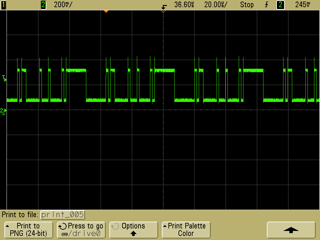
To check whether I receive data correctly at SCIA terminal of the TAPAS board from the MCU, I used an oscilloscope to view at GPIO 29 directly. This result is given below and it seemed alright.
Transmit in mainISR()
I tried sending the values 3,4,255,0 at 1 Hz in mainISR(). This resulted in garbage values as well but different from the above.
Terminal view
![]()
Simulink view
![]()
Sorry about the long post. I would like to know
1) What's wrong with SCI. Is it correctly coded?
2) How can I rectify this problem to receive the data correctly in PC from the MCU?

