This thread has been locked.

If you have a related question, please click the "Ask a related question" button in the top right corner. The newly created question will be automatically linked to this question.

LAUNCHXL-F28027: syncing ePWM blocks on Simulink

Part Number: LAUNCHXL-F28027

Hi,

I'm working on a project very similar to the example "Control of a 3-Phase Interleaved DC/DC Converter" from the ePWM reference guide, shown below. 

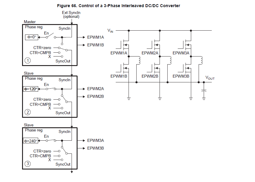
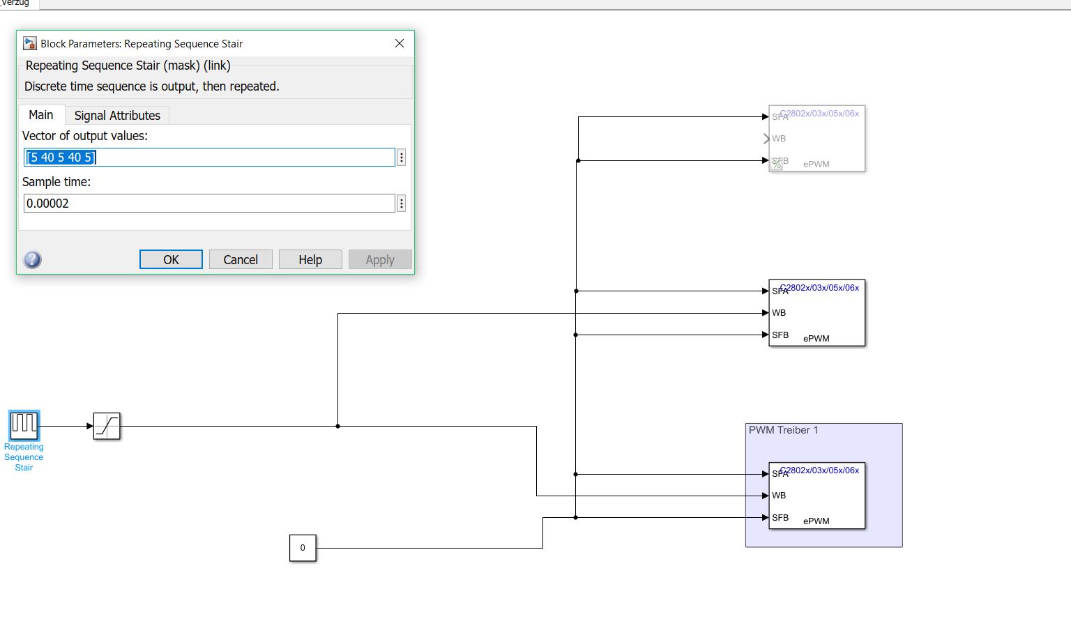
I have 3 ePWM blocks, one working as the master module, the other two as slaves 120 and 240 deg phase-shifted. I would like them to output exactly the same signal, just phase-shifted. 
My input to the ePWM blocks, which is the duty cycle (just one value for all three of them) obtained from the current values read in by three ADC blocks and their successive elaboration through a closed-loop control system, is varying because of the nature of my hardware. Even if this varies at the same frequency as my ePWM blocks, the two frequencies don't seem to be synchronised. As a consequence the three ePWM blocks read in the given duty cycle value at different moments (each when its own timer starts counting-->timer=zero. Alternative options are available, but none puts different ePWM blocks in relation with each other). This means, that if the duty cycle varies between the timer start of ePWM1 and that of ePWM2, the latter will output a different PWM signal.

Is there a way to synchronise all three PWM blocks to read in the duty cycle value at the same time, independently from their timers running at different phase angles?

Alternatively, I have tried triggering all 3 ADC blocks through the same ePWM block ( the master ), so that the current inputs and thus the processed output value for the duty cycle wouldn't change throught the whole ePWM1 timer period (master). That somehow didn't work, though. ((didn't make use of any interrupt option))

Thanks in advance for your help,

Andrea

  • Andrea,

    Are you varying the PWM's frequency?

    Note when updating the PWM's CMPx this is a known limitation of the PWM. You must define a safe period at which you can update your PWM's values, and update all PWMs during this period.

    Be sure to use Shadow Load to ensure that a CMPx event is not missed.

    Regards,
    Cody

  • Hi,

    No, I'm not varying the PWM frequency.

    I'm not sure what this shadow load is or how it can be activated, but I'm sure none of the settings I'm using are on "immediate without using shadow", if that's what you're referring to.

    How would I define a safe period to update the values, in practical terms?

    Andrea
  • Andrea,

    Often times users will determine a counter value for which the know there system will be unaffected by PWM configuration changes. For example they will only updated there values if (TBCTR <= 100), to do this they read the TBCTR and then choose to update the values or not.

    Regards,
    Cody 

  • Hi Cody,

    Thanks for your reply. If I could make sure that the PWM function block only updates the value at a specific moment inside the counter period, I would do that. Unfortunately options for that are very limited (CTR=ZERO/PERIOD/etc.). Any change in the duty cycle value between TBCTR=0 of ePWM1 and TBCTR=0 of ePWM2 would be updated by the latter only, which would output a different signal, too.

    Interestingly, I've tried feeding one and more PWM function blocks with a repeating sequence that fits exactly in a PWM period ( 5 values, each changing every fifth of a period (=100 µs because PWM frequency = 10 kHz)), as shown in picture below. 

    The result was, that ePWM1 (the lower one, the master with 0 deg shift) wouldn't always read in the value 5 or 40. And I've made sure with that sequence that acquiring the value 5 once would mean having to acquire it in the next period, too, IF the PWM block was to update the value at the exact same point in the TBCTR period. Independently from whether the sequence and the PWM period were synchronised, which I would assume should be the case.
    ( I've set "Reload for compare B Register" = "Counter equals to zero" )

    Surprisingly, ePWM1 doesn't always read the same value. It seems to be following a pattern of 5 and 40, that repeats every X periods, like 100 periods. As if the PWM period (100 µs) was slightly shorter than the sequence period and therefore shifted slowly ahead.

    These results make me something is wrong with these PWM function blocks.

    Regards,

    Andrea

  • Hi Andrea,

    We should be able to help you, please contact us at:

    https://www.mathworks.com/support/contact_us.html

  • Andrea,

    Venkatesh is the Mathworks expert, he should be able to help you with the rest of your PWM configuration on the Mathworks site.

    Thanks, and if possible post a link to that thread here to help people in the future!

    Regards,
    Cody 

  • It's easy. First, "Master" PWM is configured as shown on the left. Second and third PWMs are synchronized from the first one with 1/3 and 2/3 phase shift. That's it.

  • Hi,

    I wrote to you but still haven't got a reply.

    Best regards,

    Andrea
  • Hi,

    We got request from support channel today.
    Can we please work from the MathWorks support channel and close the thread here.
  • Sure,

    As long as you reply there. (:

    Best regards,

    Andrea