This thread has been locked.

If you have a related question, please click the "Ask a related question" button in the top right corner. The newly created question will be automatically linked to this question.

CCS/TMS320F28379D: No source available for "0x3fe493"

Part Number: TMS320F28379D
Other Parts Discussed in Thread: C2000WARE

Tool/software: Code Composer Studio

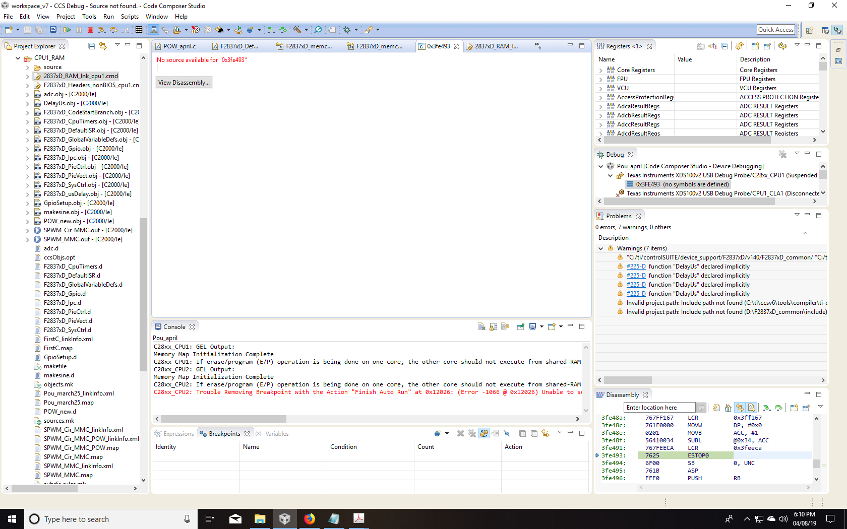
I was writing a code and when a it grew substantially large, an error "program will not fit into memory" was displayed. I tried to change the RAM link cmd file. now the program will not fit into memory error is not displayed. but I have another error now. the present error is  "No source available for "0x3fe493" Screenshot is presented below.

My previous linker file had the following memory configuration
MEMORY
{
PAGE 0 :
   /* BEGIN is used for the "boot to SARAM" bootloader mode   */

   BEGIN               : origin = 0x000000, length = 0x000002
   RAMM0               : origin = 0x000122, length = 0x0002DE
   RAMD0               : origin = 0x00B000, length = 0x000800
   RAMLS0              : origin = 0x008000, length = 0x000800
   RAMLS1              : origin = 0x008800, length = 0x000800
   RAMLS2              : origin = 0x009000, length = 0x000800
   RAMLS3              : origin = 0x009800, length = 0x000800
   RAMLS4              : origin = 0x00A000, length = 0x000800
   RESET               : origin = 0x3FFFC0, length = 0x000002

PAGE 1 :

   BOOT_RSVD       : origin = 0x000002, length = 0x000120     /* Part of M0, BOOT rom will use this for stack */
   RAMM1           : origin = 0x000400, length = 0x000400     /* on-chip RAM block M1 */
   RAMD1           : origin = 0x00B800, length = 0x000800


   RAMLS5      : origin = 0x00A800, length = 0x000800

   RAMGS0      : origin = 0x00C000, length = 0x001000
   RAMGS1      : origin = 0x00D000, length = 0x001000
   RAMGS2      : origin = 0x00E000, length = 0x001000
   RAMGS3      : origin = 0x00F000, length = 0x001000
   RAMGS4      : origin = 0x010000, length = 0x001000
   RAMGS5      : origin = 0x011000, length = 0x001000
   RAMGS6      : origin = 0x012000, length = 0x001000
   RAMGS7      : origin = 0x013000, length = 0x001000
   RAMGS8      : origin = 0x014000, length = 0x001000
   RAMGS9      : origin = 0x015000, length = 0x001000
   RAMGS10     : origin = 0x016000, length = 0x001000
   RAMGS11     : origin = 0x017000, length = 0x001000
   RAMGS12     : origin = 0x018000, length = 0x001000
   RAMGS13     : origin = 0x019000, length = 0x001000
   RAMGS14     : origin = 0x01A000, length = 0x001000
   RAMGS15     : origin = 0x01B000, length = 0x001000
   
   CPU2TOCPU1RAM   : origin = 0x03F800, length = 0x000400
   CPU1TOCPU2RAM   : origin = 0x03FC00, length = 0x000400
}


SECTIONS
{
   codestart        : > BEGIN,     PAGE = 0
   ramfuncs         : > RAMM0      PAGE = 0
   .text            : >>RAMM0 | RAMD0 |  RAMLS0 | RAMLS1 | RAMLS2 | RAMLS3 | RAMLS4,   PAGE = 0
   .cinit            : > RAMM0,     PAGE = 0
   .pinit           : > RAMM0,     PAGE = 0
   .switch          : > RAMM0,     PAGE = 0
   .reset           : > RESET,     PAGE = 0, TYPE = DSECT /* not used, */

   .stack           : > RAMM1,     PAGE = 1
   .ebss            : > RAMLS5,    PAGE = 1
   .econst          : > RAMLS5,    PAGE = 1
   .esysmem         : > RAMLS5,    PAGE = 1
   Filter_RegsFile  : > RAMGS0,       PAGE = 1

   ramgs0           : > RAMGS0,    PAGE = 1
   ramgs1           : > RAMGS1,    PAGE = 1
   
   /* The following section definitions are required when using the IPC API Drivers */
    GROUP : > CPU1TOCPU2RAM, PAGE = 1
    {
        PUTBUFFER
        PUTWRITEIDX
        GETREADIDX
    }
    
    GROUP : > CPU2TOCPU1RAM, PAGE = 1
    {
        GETBUFFER :    TYPE = DSECT
        GETWRITEIDX :  TYPE = DSECT
        PUTREADIDX :   TYPE = DSECT
    }  


    /* The following section definition are for SDFM examples */        
   Filter1_RegsFile : > RAMGS1,    PAGE = 1, fill=0x1111
   Filter2_RegsFile : > RAMGS2,    PAGE = 1, fill=0x2222
   Filter3_RegsFile : > RAMGS3,    PAGE = 1, fill=0x3333
   Filter4_RegsFile : > RAMGS4,    PAGE = 1, fill=0x4444
   Difference_RegsFile : >RAMGS5,     PAGE = 1, fill=0x3333
    
}

/*
//===========================================================================
// End of file.
//===========================================================================
*/

after I edited my RAM linker file, the memory configuration looks like this:


MEMORY
{
PAGE 0 :
   /* BEGIN is used for the "boot to SARAM" bootloader mode   */

   BEGIN               : origin = 0x000000, length = 0x000002
   RAMM0               : origin = 0x000122, length = 0x0002DE
   RAMD0               : origin = 0x00B000, length = 0x000800

   RAMLS0              : origin = 0x008000, length = 0x000800
   RAMLS1              : origin = 0x008800, length = 0x000800
   RAMLS2              : origin = 0x009000, length = 0x000800
   RAMLS3              : origin = 0x009800, length = 0x000800
   RAMLS4              : origin = 0x00A000, length = 0x000800
   RESET               : origin = 0x3FFFC0, length = 0x000002
   RAMGS6           : origin = 0x012000, length = 0x001000

PAGE 1 :

   BOOT_RSVD       : origin = 0x000002, length = 0x000120     /* Part of M0, BOOT rom will use this for stack */
   RAMM1           : origin = 0x000400, length = 0x000400     /* on-chip RAM block M1 */
   RAMD1            : origin = 0x00B800, length = 0x000800


   RAMLS5      : origin = 0x00A800, length = 0x000800

   RAMGS0      : origin = 0x00C000, length = 0x001000
   RAMGS1      : origin = 0x00D000, length = 0x001000
   RAMGS2      : origin = 0x00E000, length = 0x001000
   RAMGS3      : origin = 0x00F000, length = 0x001000
   RAMGS4      : origin = 0x010000, length = 0x001000
   RAMGS5      : origin = 0x011000, length = 0x001000

   RAMGS7      : origin = 0x013000, length = 0x001000
   RAMGS8      : origin = 0x014000, length = 0x001000
   RAMGS9      : origin = 0x015000, length = 0x001000
   RAMGS10     : origin = 0x016000, length = 0x001000
   RAMGS11     : origin = 0x017000, length = 0x001000
   RAMGS12     : origin = 0x018000, length = 0x001000
   RAMGS13     : origin = 0x019000, length = 0x001000
   RAMGS14     : origin = 0x01A000, length = 0x001000
   RAMGS15     : origin = 0x01B000, length = 0x001000
   
   CPU2TOCPU1RAM   : origin = 0x03F800, length = 0x000400
   CPU1TOCPU2RAM   : origin = 0x03FC00, length = 0x000400
}


SECTIONS
{
   codestart        : > BEGIN,     PAGE = 0
   ramfuncs         : > RAMM0      PAGE = 0
   .text            : >>RAMM0 | RAMD0 |  RAMLS0 | RAMLS1 | RAMLS2 | RAMLS3 | RAMLS4 |RAMGS6,   PAGE = 0
   .cinit           : > RAMM0,     PAGE = 0
   .pinit           : > RAMLS0,     PAGE = 0
   .switch          : > RAMM0,     PAGE = 0
   .reset           : > RESET,     PAGE = 0, TYPE = DSECT /* not used, */

   .stack           : > RAMM1,     PAGE = 1
   .ebss            : > RAMLS5,    PAGE = 1
   .econst          : > RAMLS5,    PAGE = 1
   .esysmem         : > RAMLS5,    PAGE = 1
   Filter_RegsFile  : > RAMGS0,       PAGE = 1

   ramgs0           : > RAMGS0,    PAGE = 1
   ramgs1           : > RAMGS1,    PAGE = 1
   
   /* The following section definitions are required when using the IPC API Drivers */
    GROUP : > CPU1TOCPU2RAM, PAGE = 1
    {
        PUTBUFFER
        PUTWRITEIDX
        GETREADIDX
    }
    
    GROUP : > CPU2TOCPU1RAM, PAGE = 1
    {
        GETBUFFER :    TYPE = DSECT
        GETWRITEIDX :  TYPE = DSECT
        PUTREADIDX :   TYPE = DSECT
    }  


    /* The following section definition are for SDFM examples */        
   Filter1_RegsFile : > RAMGS1,    PAGE = 1, fill=0x1111
   Filter2_RegsFile : > RAMGS2,    PAGE = 1, fill=0x2222
   Filter3_RegsFile : > RAMGS3,    PAGE = 1, fill=0x3333
   Filter4_RegsFile : > RAMGS4,    PAGE = 1, fill=0x4444
   Difference_RegsFile : >RAMGS5,     PAGE = 1, fill=0x3333
    
}

/*
//===========================================================================
// End of file.
//===========================================================================
*/

please help me to solve the problem

  • Please take a look at the tips Ken provided at e2e.ti.com/.../788037 and also the other link he points to.
  • in the link provided by you, the problem was related to boot rom. I am not sure of where the problem occurs in my case. hence i could not use the solution by Ken. Could you please point out where the problem lies in my case ?

  • Rupak,

    The F28379D address 0x3fe493 is located in the boot ROM. Can you view the disassembly by clicking on the "View Disassembly..." button? If so, try running to main() by clicking on Run -> Go Main. Do you get there?

    - Ken
  • Thanks Ken. Yes it is in the Boot rom. it is defined in the Ram link cmd file. Why the program counter is not able to come out of the boot ROM and is stopping at ESTOP0 is still not clear to me. Could you please explain to me why this is happening?

  • Rupak,

    Did you remember to set the EMU_KEY and EMU_BMODE? Below please find the link to the F28379D workshop:

    See lab exercise 5, step 12

    Also, compare you project to the workshop code and check if you can narrow down the issue.

    I hope this helps. If this answers your question, please click the green "Verified Answer" button. Thanks.

    - Ken
  • Rupak,

    It's been a while since I have heard from you last. Therefore, I am assuming that my last reply resolve your issue. If this isn’t the case, please reject this resolution or reply to this thread. If this thread locks, please make a new thread describing the current status of your issue. Thank you.

    - Ken
  • thanks a lot for your suggestions Ken. I shall come back to this thread in a few days..

  • Hello Ken . The codestart in my program disables the Watchdog.


    WD_DISABLE    .set    1        ;set to 1 to disable WD, else set to 0

        .ref _c_int00
        .global code_start

    ***********************************************************************
    * Function: codestart section
    *
    * Description: Branch to code starting point
    ***********************************************************************

        .sect "codestart"

    code_start:
        .if WD_DISABLE == 1
            LB wd_disable       ;Branch to watchdog disable code
        .else
            LB _c_int00         ;Branch to start of boot._asm in RTS library
        .endif

    Lab 5 exercise 12 says there is a restart because of the WD. since Wd is disabled in my case, it should not reset in the first place. moreoever, it says to set the bootloader mode by setting it to EMU_BOOT_SARAm. i have tried that but to no use. Also, could you please help me on how and where to set the EMU_KEY and EMU BMODE ?

  • Rupak,

    In the CodeStartBranch.asm file the watchdog is disabled, however in the watchdog.c file the watchdog is enabled for the lab exercises. To set the boot mode you need to be in the CCS Debug perspective view. At the top you will see "Scripts". Follow the directions for step 12 for loading values into EMU_KEY and EMU BMODE.

    I hope this helps. If this answers your question, please click the green "Verified Answer" button. Thanks.

    - Ken
  •  Hello Ken

    I have already tried to set the bootloader mode by setting it to EMU_BOOT_SARAM. this has not helped. Still, it shows No source available for "0x3fe493"

  • Rupak,

    Again, "No source available..." is not an error. Please see:

    e2e.ti.com/.../2412239

    Also, from your screen capture, it looks like you have number of warnings that need to be fixed first. Your screen capture does not have the active project open, so it is hard to tell what the issue is.

    - Ken
  • Thanks Ken.

    I understand that this is not an error. the piece of code is written in Assembly and not in C. i have checked it. it in indeed in  assembly in the file boot28.asm, but i need to solve this problem. What should be done to solve this issue? im attaching my program here. this program is linked to some of the initialization files in control suite.

    Pou_april.zip

  • Rupak,

    Since "No source available..." is NOT an error, then there is NO problem to solve. I have already supplied you with information on how see the ROM source code and how to the add symbols along with selecting the ROM COFF file.

    In general, we do not review or debug user code, but we will provide assistance to you with specific issues relating to our devices and development tools. This includes clarifying the behavior of any bit, register, or features when designing with our devices. Please note that all peripherals have example code in C2000Ware. We suggest comparing your code to the example code to determine where the problem may exist. It is recommended to follow standard and logical debugging techniques. Please continue to debug your code and feel free to use this forum to ask specific questions. The more specific the question, the better we can assist you.

    - Ken
  • e2e.ti.com/.../1876684

    the above post by kyle cousino solved the problem. Thanks ken for all the support.