This thread has been locked.
If you have a related question, please click the "Ask a related question" button in the top right corner. The newly created question will be automatically linked to this question.
Tool/software: Code Composer Studio
Hi,
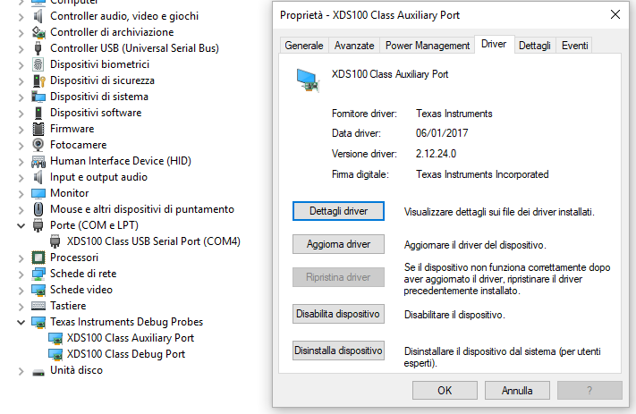
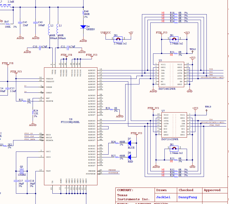
I installed on my PC the drivers of XDS100V2 emulation controller and I enabled the Virtual Com Port on the TI auxiliarity port (COM4) but the board doesn't communicate with PC through SCIA. The program that I loaded on the FLASH memory was generated by Simulink and it consists in a costant linked to SCI-A writing block.
On simulink I directly selected Launchpad F28379D as board in use and pins 42 and 43 were automatically associated to SCI-A.
I tested demo which is available in ControlSuite but the communication failed.
As terminal, I used both CCS and Teraterm.
Is there another example to test serial usb port? What is the solution?
Thanks for the answers.
Here you are the screen shot of Windows Device Manager.
I enabled VCP only for the auxiliary port.
When I enabled VCP for the debug port, too, there was a conflict with loading and debug operation if I opened its associated port (COM3). So I disabled VCP for it.
Do you mean the debug port as primary channel?
Marco,
Thanks for sending the screenshot, this looks good, in terms of both the emulation channel and UART channel are present. Sorry if I confused matters, you are correct that the primary debug port does not need VCP enabled.
It looks like you have followed the steps in the link below; but can you confirm?
Best,
Matthew
Hi,
Thank you for the support.
About the steps shown in the link: yes, I did.
Regards.
I've uninstalled the drivers and then i've installed CC6 (the last version described in the link) in order to have older and different(?) drivers. Now the board is detected as TI XDS100 Channel A and TI XDS100 Channel B. Although I follow the steps in the link, the result is the same: it doesn't communicate by COM.
Marco,
Understand you are using Simulink; would it be possible for you to download and install our C2000Ware SW package?
There is a SCI Echoback example here: C:\ti\c2000\C2000Ware_1_00_06_00\device_support\f2806x\examples\c28\sci_echoback\ that I'd like to use standalone to see if we can detect comms with this and hyperterm(or whatever program you normally use for UART comms to the PC).
This will tell us if the HW is the issue or the link to the Mathworks receiver.
Best,
Matthew
I've just tested the example "sci_echoback" for my board and the result is the same. I've used "teraterm" to test it. Yesterday I read only the comment (in "Example_2837xDSci_Echoback.c") of the example and I could see that gpio 28 and 29 are used for communication. By reading the program, I can notice that pin 42-43 are set for SCIA.
I've also tested a program built in Simulink for SCIA (the same echoback used for SCIB which I talked about in the previous post) by setting both gpio 42-43 and gpio 28-29 for communication but the SCIA continues not to work.
Marco,
Apologies on referencing the F28069 source files, you found the correct equivalent for your device in C2000Ware.
I'd like to probe the signals at the ISO chip boundaries to see if we actually see either the TX or RX lines toggle.
From the below let's look at U5 pin 11(RX pin) and U7 pin 4(TX pin). If we see signal activity here, we can go to the other side of the ISO device and make sure we see it translating things correctly.
If the initial pins are dead we can go from there.