
- Ask a related questionWhat is a related question?A related question is a question created from another question. When the related question is created, it will be automatically linked to the original question.

Hi all,
I have a strange problem where in the Phase offset is always turning out to be more by 2 EPWM Clock Cycle.
I have updated the TI code file epwm_updown_aq_cpu01.c to put code to generate ePWM output from ePWM1A.
Generate a Sync out from ePWM1A to ePWM2A. React on the sync signal with phase offset for ePWM2A.
But the phase is always 2 clock cycle more.
Attached is the code:
void InitEPwm1Example()
{
//
// Setup TBCLK
//
EPwm1Regs.TBPRD = 10000; // Set timer period 801 TBCLKs
EPwm1Regs.TBPHS.bit.TBPHS = 0x0000; // Phase is 0
EPwm1Regs.TBCTR = 0x0000; // Clear counter
//
// Set Compare values
//
EPwm1Regs.CMPA.bit.CMPA = 5000; // Set compare A value
//EPwm1Regs.CMPB.bit.CMPB = EPWM1_MAX_CMPB; // Set Compare B value
//
// Setup counter mode
//
EPwm1Regs.TBCTL.bit.CTRMODE = TB_COUNT_UPDOWN; // Count up and down
EPwm1Regs.TBCTL.bit.PHSEN = TB_DISABLE; // Disable phase loading
EPwm1Regs.TBCTL.bit.HSPCLKDIV = TB_DIV1; // Clock ratio to SYSCLKOUT
EPwm1Regs.TBCTL.bit.CLKDIV = TB_DIV1;
EPwm1Regs.TBCTL.bit.SYNCOSEL = 0x1;
//
// Setup shadowing
//
EPwm1Regs.CMPCTL.bit.SHDWAMODE = CC_SHADOW;
EPwm1Regs.CMPCTL.bit.SHDWBMODE = CC_SHADOW;
EPwm1Regs.CMPCTL.bit.LOADAMODE = CC_CTR_ZERO; // Load on Zero
EPwm1Regs.CMPCTL.bit.LOADBMODE = CC_CTR_ZERO;
EPwm1Regs.AQCTLA.all = 0x60;
}
void InitEPwm2Example()
{
//
// Setup TBCLK
//
EPwm2Regs.TBPRD = 10000; // Set timer period 801 TBCLKs
EPwm2Regs.TBPHS.bit.TBPHS = 2500; // Phase is 0
EPwm2Regs.TBCTR = 0x0000; // Clear counter
//
// Set Compare values
//
EPwm2Regs.CMPA.bit.CMPA = 5000; // Set compare A value
// EPwm2Regs.CMPB.bit.CMPB = EPWM2_MIN_CMPB; // Set Compare B value
//
// Setup counter mode
//
EPwm2Regs.TBCTL.bit.CTRMODE = TB_COUNT_UPDOWN; // Count up and down
EPwm2Regs.TBCTL.bit.PHSEN = TB_ENABLE; // Disable phase loading
EPwm2Regs.TBCTL.bit.HSPCLKDIV = TB_DIV1; // Clock ratio to SYSCLKOUT
EPwm2Regs.TBCTL.bit.CLKDIV = TB_DIV1;
//
// Setup shadowing
//
EPwm2Regs.CMPCTL.bit.SHDWAMODE = CC_SHADOW;
EPwm2Regs.CMPCTL.bit.SHDWBMODE = CC_SHADOW;
EPwm2Regs.CMPCTL.bit.LOADAMODE = CC_CTR_ZERO; // Load on Zero
EPwm2Regs.CMPCTL.bit.LOADBMODE = CC_CTR_ZERO;
EPwm2Regs.AQCTLA.all = 0x60;
}
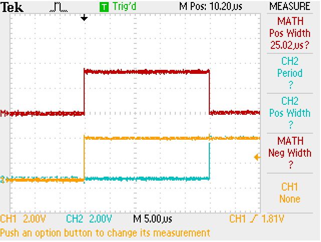
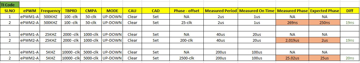
The figure is for the last case from the table.
Please let me know if I am missing anything here.


