This thread has been locked.

If you have a related question, please click the "Ask a related question" button in the top right corner. The newly created question will be automatically linked to this question.

CCS/TMS320F28379D: Error connecting to the target: (Error -2131 @ 0x0)

Part Number: TMS320F28379D
Other Parts Discussed in Thread: C2000WARE, TMDSCNCD28379D

Tool/software: Code Composer Studio

I have been working with this board for a year now, and I've encountered a lot of problems that I was able to solve, but this one I can't seem to find a solution. I'm getting this error when trying to debug since yesterday.

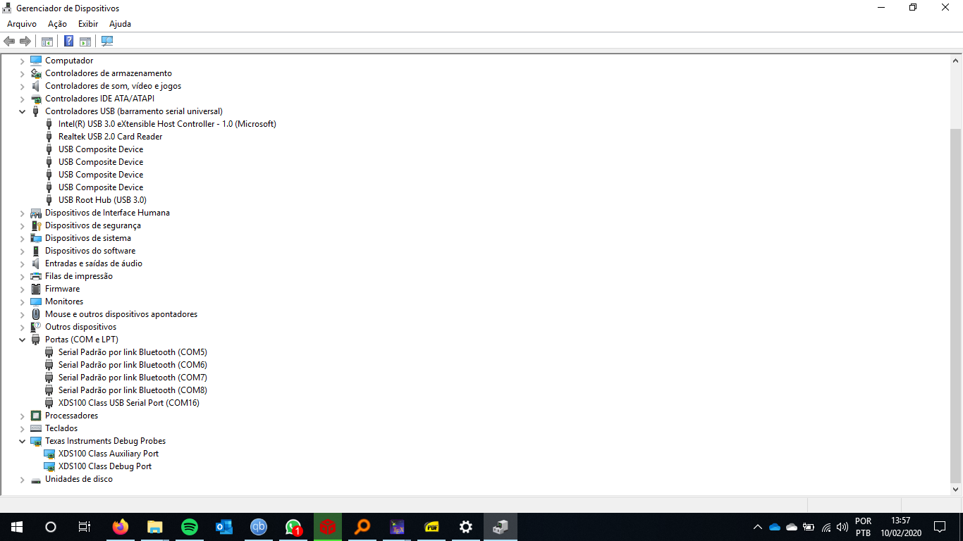
I gone through the C2000 MCU JTAG Connectivity Debug pdf but I wasn't able to find the TRSTn and XRSn pins in my control board, also in the doc it seems that it's supposed to be 3 entries in device manager, as below.

Also when tinkering with the debugging configurations (trying to find "Modify the CCS "On Connect" Action" wich i wasn't able to) I changed something that made my debugged not automatically connect.

Any help is appreciated.

  • Hi Arthur,

    Open the target configuration file, and go to advanced tab. Then run "Test Connection".

    This should show more detailed information on JTAG connectivity issue.

    Please refer to the Application note which goes through steps on how to debug JTAG connectivity.


  • This is what I get.

    [Start: Texas Instruments XDS100v2 USB Debug Probe]

    Execute the command:

    %ccs_base%/common/uscif/dbgjtag -f %boarddatafile% -rv -o -F inform,logfile=yes -S pathlength -S integrity

    [Result]


    -----[Print the board config pathname(s)]------------------------------------

    C:\Users\anrl\AppData\Local\TEXASI~1\CCS\
        ccs920\0\0\BrdDat\testBoard.dat

    -----[Print the reset-command software log-file]-----------------------------

    This utility has selected a 100- or 510-class product.
    This utility will load the adapter 'jioserdesusb.dll'.
    The library build date was 'Nov 25 2019'.
    The library build time was '16:55:29'.
    The library package version is '8.4.0.00006'.
    The library component version is '35.35.0.0'.
    The controller does not use a programmable FPGA.
    The controller has a version number of '4' (0x00000004).
    The controller has an insertion length of '0' (0x00000000).
    This utility will attempt to reset the controller.
    This utility has successfully reset the controller.

    -----[Print the reset-command hardware log-file]-----------------------------

    The scan-path will be reset by toggling the JTAG TRST signal.
    The controller is the FTDI FT2232 with USB interface.
    The link from controller to target is direct (without cable).
    The software is configured for FTDI FT2232 features.
    The controller cannot monitor the value on the EMU[0] pin.
    The controller cannot monitor the value on the EMU[1] pin.
    The controller cannot control the timing on output pins.
    The controller cannot control the timing on input pins.
    The scan-path link-delay has been set to exactly '0' (0x0000).

    -----[The log-file for the JTAG TCLK output generated from the PLL]----------

    There is no hardware for programming the JTAG TCLK frequency.

    -----[Measure the source and frequency of the final JTAG TCLKR input]--------

    There is no hardware for measuring the JTAG TCLK frequency.

    -----[Perform the standard path-length test on the JTAG IR and DR]-----------

    This path-length test uses blocks of 64 32-bit words.

    The test for the JTAG IR instruction path-length failed.
    The JTAG IR instruction scan-path is stuck-at-ones.

    The test for the JTAG DR bypass path-length failed.
    The JTAG DR bypass scan-path is stuck-at-ones.

    -----[Perform the Integrity scan-test on the JTAG IR]------------------------

    This test will use blocks of 64 32-bit words.
    This test will be applied just once.

    Do a test using 0xFFFFFFFF.
    Scan tests: 1, skipped: 0, failed: 0
    Do a test using 0x00000000.
    Test 2 Word 0: scanned out 0x00000000 and scanned in 0xFFFFFFFF.
    Test 2 Word 1: scanned out 0x00000000 and scanned in 0xFFFFFFFF.
    Test 2 Word 2: scanned out 0x00000000 and scanned in 0xFFFFFFFF.
    Test 2 Word 3: scanned out 0x00000000 and scanned in 0xFFFFFFFF.
    Test 2 Word 4: scanned out 0x00000000 and scanned in 0xFFFFFFFF.
    Test 2 Word 5: scanned out 0x00000000 and scanned in 0xFFFFFFFF.
    Test 2 Word 6: scanned out 0x00000000 and scanned in 0xFFFFFFFF.
    Test 2 Word 7: scanned out 0x00000000 and scanned in 0xFFFFFFFF.
    The details of the first 8 errors have been provided.
    The utility will now report only the count of failed tests.
    Scan tests: 2, skipped: 0, failed: 1
    Do a test using 0xFE03E0E2.
    Scan tests: 3, skipped: 0, failed: 2
    Do a test using 0x01FC1F1D.
    Scan tests: 4, skipped: 0, failed: 3
    Do a test using 0x5533CCAA.
    Scan tests: 5, skipped: 0, failed: 4
    Do a test using 0xAACC3355.
    Scan tests: 6, skipped: 0, failed: 5
    Some of the values were corrupted - 83.3 percent.

    The JTAG IR Integrity scan-test has failed.

    -----[Perform the Integrity scan-test on the JTAG DR]------------------------

    This test will use blocks of 64 32-bit words.
    This test will be applied just once.

    Do a test using 0xFFFFFFFF.
    Scan tests: 1, skipped: 0, failed: 0
    Do a test using 0x00000000.
    Test 2 Word 0: scanned out 0x00000000 and scanned in 0xFFFFFFFF.
    Test 2 Word 1: scanned out 0x00000000 and scanned in 0xFFFFFFFF.
    Test 2 Word 2: scanned out 0x00000000 and scanned in 0xFFFFFFFF.
    Test 2 Word 3: scanned out 0x00000000 and scanned in 0xFFFFFFFF.
    Test 2 Word 4: scanned out 0x00000000 and scanned in 0xFFFFFFFF.
    Test 2 Word 5: scanned out 0x00000000 and scanned in 0xFFFFFFFF.
    Test 2 Word 6: scanned out 0x00000000 and scanned in 0xFFFFFFFF.
    Test 2 Word 7: scanned out 0x00000000 and scanned in 0xFFFFFFFF.
    The details of the first 8 errors have been provided.
    The utility will now report only the count of failed tests.
    Scan tests: 2, skipped: 0, failed: 1
    Do a test using 0xFE03E0E2.
    Scan tests: 3, skipped: 0, failed: 2
    Do a test using 0x01FC1F1D.
    Scan tests: 4, skipped: 0, failed: 3
    Do a test using 0x5533CCAA.
    Scan tests: 5, skipped: 0, failed: 4
    Do a test using 0xAACC3355.
    Scan tests: 6, skipped: 0, failed: 5
    Some of the values were corrupted - 83.3 percent.

    The JTAG DR Integrity scan-test has failed.

    [End: Texas Instruments XDS100v2 USB Debug Probe]

    I already been through that, but, as said in the original post I haven't been able to find some pins and configurations it asks to find and test.

  • Hello, my board is a TI controlcard docking station R4.1, it seems its not a problem with drivers, i got an exact same board and it works normally.

    Can I do something or is this malfunctioning board essentially dead?

    Both the ISO JTAG logic and and the controlcard power leds are on, I found the TRSTn and XRSn and both are inactive high as expected. My CCS and drivers are up to date. I can see the probe in device manager and in the FT_prog.exe. But I can`t debug it.

  • Arthur,

    As it is working OK with other device, so we can rule out a driver issue. 


    Can you take a picture of the Windows Device Manager with both the good and bad boards?  In your previous picture(which we assume is the bad board) it is only showing 1 XDS100 connection, when there should be 2(1 for the emulator, the other the SCI back channel). 

    If the good board shows 2 XDS100, we may need to re-program the FDTI chip as show in the JTAG debug app note.

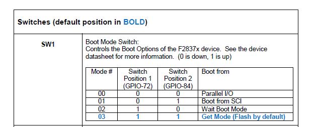
     Also, please put the device in Wait Boot Mode, to rule out the program/flash execution blocking emulator access. 

  • Thanks for the patience.

    I already tried wait boot mode, to no avail. Right now I can only print device manager on monday now. I`ll try to reprogram the ftdi chip also on monday.

    Thanks again for the responses, I`ll get back to you.

  • As asked here are the pictures:

    The first one is the working board

    the second one is the malfunctioning board

    As you can see, both look the same, the only difference I can see is the COM port number.

    Thanks for your help.

  • Arthur,

    It sounds like hardware issue.

    Can you confirm that the switch configurations are the same between working and non-working boards?

    Did you also try reprogramming the FTDI chip?

  • I also tried to reprogram the ftdi chip, wich also did nothing.

    If it`s a hardware issue theres no helping it then right?

  • I will loop hardware expert if he has any input.

  • Please refer to link below. Can you try the workaround suggested here?

    e2e.ti.com/.../715730

  • Arthur,

    you will receive this error when the JTAG emulator is working and the C2000 device is not responding to the messages. I do not think this is a problem with your emulator.

    This most commonly happens when people forget to power the controlCARD, don't forget that the C2000 is isolated from the emulator in this design. I assume this isn't the case for you if you have previously used this successfully, but I wanted to point it out.

    1. Is the device getting hot?
    2. What is the voltage on TP5?
    3. What is the voltage on TP6?
    4. What is the voltage on TP2?

    Please send a photo of your test setup running. All cables connected and switches set as if you were using the device. Maybe this will show something.

    Thanks,
    Cody 

  • Hello Santosh, I don't understand how to use the jtag on the docking station. I tried external source and the problems still happens.

  • Hello Cody, this is how I'm using this device now.

    I can't seem to find these pins on the pinout document. Could you point me to where they are?

  • Arthur,

    If you have installed C2000ware, then it should be at

    C:\ti\C2000Ware_2_01_00_00\boards\controlCARDs\TMDSCNCD28379D\R1_3

  • Arthur,

    TPx is not in the pinout document because it is not part of the pinout. "TP" stands for 'test point', they are small pads scattered across the PCB which you can used to observe or "test" as circuit. They look like a large via which isn't tented.

    TP5 is near the emulator(left side as you look at the device)

    TP6 is in the lower right near the power supply

    TP2 is to the right on the TMS320 device in the middle of the PCB.


    Regards,
    Cody 

  • Arthur,

    Are you still having JTAG issue or it has been resolved?

  • Hello, I'm still having issues, but I cannot work with this board for some weeks, can you leave this thread open or should I create another one when i get the opportunity to test it?

  • Please create a new one when you are ready to debug further.