This thread has been locked.

If you have a related question, please click the "Ask a related question" button in the top right corner. The newly created question will be automatically linked to this question.

TMDSCNCD28035ISO: Blocked ISOCard TMS320F28035

Part Number: TMDSCNCD28035ISO
Other Parts Discussed in Thread: TMS320F28035

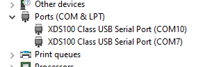
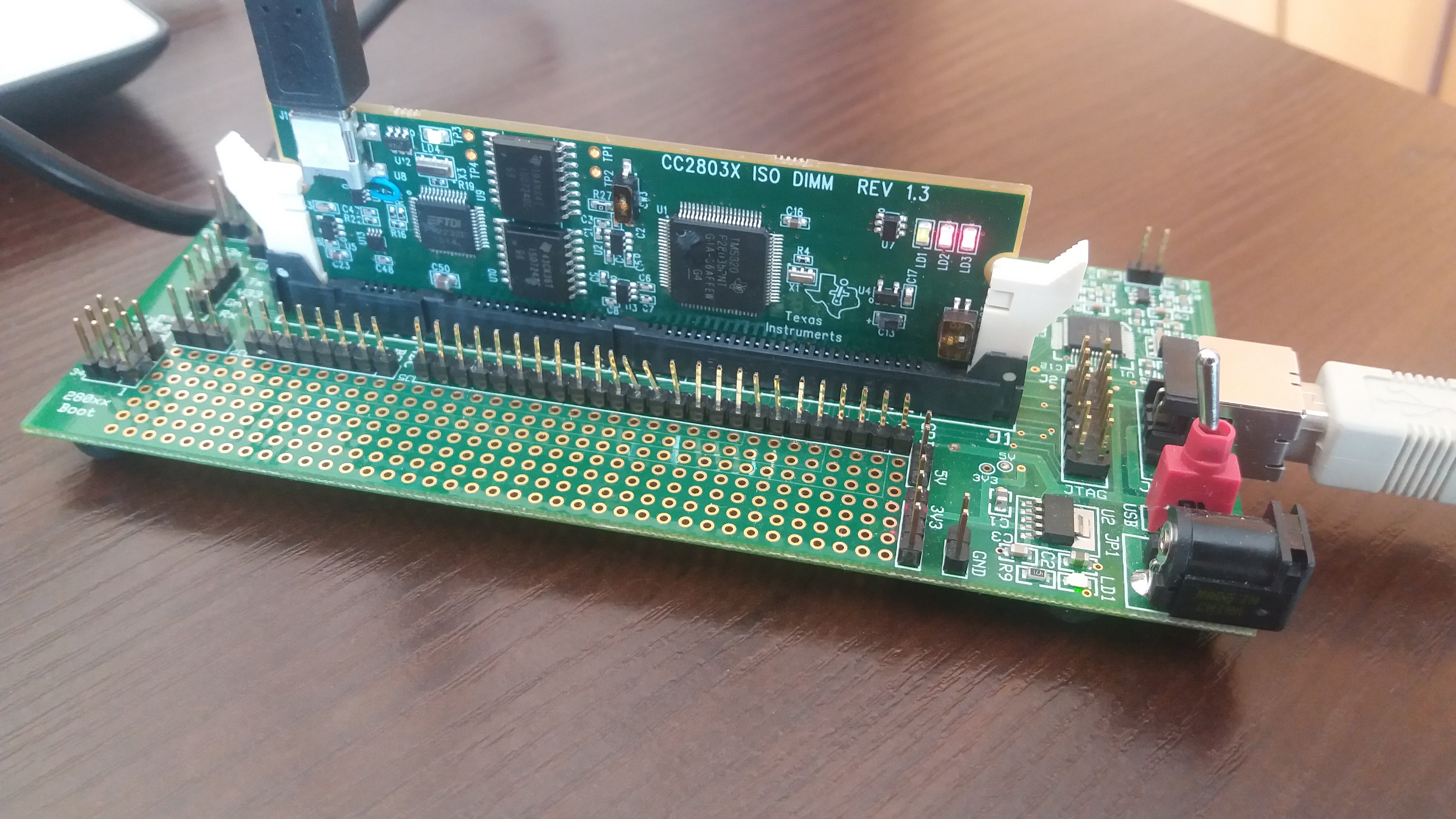
By mistake, I try to put out ISOCARD, when it was still on power. Due to this the CARD is probably blocked. When I try to debug any session, while using this card I have a message: 

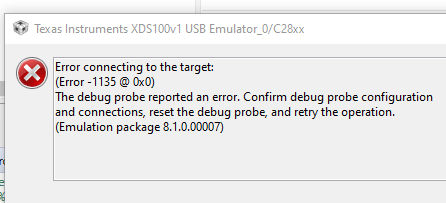
Alos led LD2 is constantly red.

I try to erase Flash by UNUIFLASH, but when I go to Settings & Utilities -> Erase Sector Selection -> Erase Flash I also receive an error.

Is there any way to unlock this device?

  • Let's try and get the device in Wait Boot mode which will keep the device from executing any code, and potentially entering secure mode.

    Ensure the the switches on the control card are in the following posistions.

    SW2: Pos1 is down/off  Pos2 is up/on

    SW3: is down/on

    Try powering up with these settings and trying your connection; just right click on your target config file .ccxml and "Launch configuration"  Then manually hover over the C28x core and "Connect"

    Assuming we do get a connection, open a memory window to address 0x3F7FF8 and make sure that addresses through 0x3F8000 are visible.  Refresh the window and let me know what you see.  If it is all 0xFFFF then the device is erased and unsecure and you should be able to continue debug.  If you still see 0x0000 then there is a password programmed into the device and it is locked.

    Will go from there once you are able to try the above.

    Best,

    Matthew

  • Thank you for response.

    Unfortunately after click "Connect Target" I got the same error.

  • When you connect to the USB port that is the XDS100v1 debug probe, do you see this enumerate in the Windows Device Config?  You should see 2 XDS100 class devices, one is the emulator the other is a UART channel.

    Best,

    Matthew

  • Yes I can see 2 devices.

  • That's good news, we don't have to re-program the FTDI chip.

    Can you double click on your .ccxml file to show the settings for both the emulator and the target?

    Best,
    Matt

  • Yes,

    <?xml version="1.0" encoding="UTF-8" standalone="no"?>
    <configurations XML_version="1.2" id="configurations_0">
        <configuration XML_version="1.2" id="Texas Instruments XDS100v1 USB Debug Probe_0">
            <instance XML_version="1.2" desc="Texas Instruments XDS100v1 USB Debug Probe_0" href="connections/TIXDS100usb_Connection.xml" id="Texas Instruments XDS100v1 USB Debug Probe_0" xml="TIXDS100usb_Connection.xml" xmlpath="connections"/>
            <connection XML_version="1.2" id="Texas Instruments XDS100v1 USB Debug Probe_0">
                <instance XML_version="1.2" href="drivers/tixds100c28x.xml" id="drivers" xml="tixds100c28x.xml" xmlpath="drivers"/>
                <instance XML_version="1.2" href="drivers/tixds100cla.xml" id="drivers" xml="tixds100cla.xml" xmlpath="drivers"/>
                <platform XML_version="1.2" id="platform_0">
                    <instance XML_version="1.2" desc="Experimenter's Kit - Piccolo F28035_0" href="boards/expkitF28035.xml" id="Experimenter's Kit - Piccolo F28035_0" xml="expkitF28035.xml" xmlpath="boards"/>
                </platform>
            </connection>
        </configuration>
    </configurations>

    it looks like this:

  • Let's try 2 things:

    1)In the CCXML settings, under the Basic tab, let's change the Board/Device type from experimenters kit to just TMS320F28035 device, then make sure to "Save" the config

    2)Now push the "Test Connection" button and send that dialog ouput back to this thread and I'll look at it.

    Best,

    Matthew

  • Hello,

    this the outout:

    [Start: Texas Instruments XDS100v1 USB Debug Probe_0]

    Execute the command:

    %ccs_base%/common/uscif/dbgjtag -f %boarddatafile% -rv -o -F inform,logfile=yes -S pathlength -S integrity

    [Result]


    -----[Print the board config pathname(s)]------------------------------------

    C:\Users\Midgard\AppData\Local\TEXASI~1\
    CCS\ccs901\0\0\BrdDat\testBoard.dat

    -----[Print the reset-command software log-file]-----------------------------

    This utility has selected a 100- or 510-class product.
    This utility will load the adapter 'jioserdesusb.dll'.
    The library build date was 'Mar 25 2019'.
    The library build time was '17:36:26'.
    The library package version is '8.1.0.00007'.
    The library component version is '35.35.0.0'.
    The controller does not use a programmable FPGA.
    The controller has a version number of '4' (0x00000004).
    The controller has an insertion length of '0' (0x00000000).
    This utility will attempt to reset the controller.
    This utility has successfully reset the controller.

    -----[Print the reset-command hardware log-file]-----------------------------

    The scan-path will be reset by toggling the JTAG TRST signal.
    The controller is the FTDI FT2232 with USB interface.
    The link from controller to target is direct (without cable).
    The software is configured for FTDI FT2232 features.
    The controller cannot monitor the value on the EMU[0] pin.
    The controller cannot monitor the value on the EMU[1] pin.
    The controller cannot control the timing on output pins.
    The controller cannot control the timing on input pins.
    The scan-path link-delay has been set to exactly '0' (0x0000).

    -----[The log-file for the JTAG TCLK output generated from the PLL]----------

    There is no hardware for programming the JTAG TCLK frequency.

    -----[Measure the source and frequency of the final JTAG TCLKR input]--------

    There is no hardware for measuring the JTAG TCLK frequency.

    -----[Perform the standard path-length test on the JTAG IR and DR]-----------

    This path-length test uses blocks of 64 32-bit words.

    The test for the JTAG IR instruction path-length failed.
    The JTAG IR instruction scan-path is stuck-at-ones.

    The test for the JTAG DR bypass path-length failed.
    The JTAG DR bypass scan-path is stuck-at-ones.

    -----[Perform the Integrity scan-test on the JTAG IR]------------------------

    This test will use blocks of 64 32-bit words.
    This test will be applied just once.

    Do a test using 0xFFFFFFFF.
    Scan tests: 1, skipped: 0, failed: 0
    Do a test using 0x00000000.
    Test 2 Word 0: scanned out 0x00000000 and scanned in 0xFFFFFFFF.
    Test 2 Word 1: scanned out 0x00000000 and scanned in 0xFFFFFFFF.
    Test 2 Word 2: scanned out 0x00000000 and scanned in 0xFFFFFFFF.
    Test 2 Word 3: scanned out 0x00000000 and scanned in 0xFFFFFFFF.
    Test 2 Word 4: scanned out 0x00000000 and scanned in 0xFFFFFFFF.
    Test 2 Word 5: scanned out 0x00000000 and scanned in 0xFFFFFFFF.
    Test 2 Word 6: scanned out 0x00000000 and scanned in 0xFFFFFFFF.
    Test 2 Word 7: scanned out 0x00000000 and scanned in 0xFFFFFFFF.
    The details of the first 8 errors have been provided.
    The utility will now report only the count of failed tests.
    Scan tests: 2, skipped: 0, failed: 1
    Do a test using 0xFE03E0E2.
    Scan tests: 3, skipped: 0, failed: 2
    Do a test using 0x01FC1F1D.
    Scan tests: 4, skipped: 0, failed: 3
    Do a test using 0x5533CCAA.
    Scan tests: 5, skipped: 0, failed: 4
    Do a test using 0xAACC3355.
    Scan tests: 6, skipped: 0, failed: 5
    Some of the values were corrupted - 83.3 percent.

    The JTAG IR Integrity scan-test has failed.

    -----[Perform the Integrity scan-test on the JTAG DR]------------------------

    This test will use blocks of 64 32-bit words.
    This test will be applied just once.

    Do a test using 0xFFFFFFFF.
    Scan tests: 1, skipped: 0, failed: 0
    Do a test using 0x00000000.
    Test 2 Word 0: scanned out 0x00000000 and scanned in 0xFFFFFFFF.
    Test 2 Word 1: scanned out 0x00000000 and scanned in 0xFFFFFFFF.
    Test 2 Word 2: scanned out 0x00000000 and scanned in 0xFFFFFFFF.
    Test 2 Word 3: scanned out 0x00000000 and scanned in 0xFFFFFFFF.
    Test 2 Word 4: scanned out 0x00000000 and scanned in 0xFFFFFFFF.
    Test 2 Word 5: scanned out 0x00000000 and scanned in 0xFFFFFFFF.
    Test 2 Word 6: scanned out 0x00000000 and scanned in 0xFFFFFFFF.
    Test 2 Word 7: scanned out 0x00000000 and scanned in 0xFFFFFFFF.
    The details of the first 8 errors have been provided.
    The utility will now report only the count of failed tests.
    Scan tests: 2, skipped: 0, failed: 1
    Do a test using 0xFE03E0E2.
    Scan tests: 3, skipped: 0, failed: 2
    Do a test using 0x01FC1F1D.
    Scan tests: 4, skipped: 0, failed: 3
    Do a test using 0x5533CCAA.
    Scan tests: 5, skipped: 0, failed: 4
    Do a test using 0xAACC3355.
    Scan tests: 6, skipped: 0, failed: 5
    Some of the values were corrupted - 83.3 percent.

    The JTAG DR Integrity scan-test has failed.

    [End: Texas Instruments XDS100v1 USB Debug Probe_0]

  • Thanks for the new info: looking at this document http://dev.ti.com/tirex/explore/node?node=ALCbEC2BHQ6M0pTWLeQ69Q__gYkahfz__LATEST  can you let me know the state of the LEDs on the ISO CARD when powered?  LD1 and LD4 are the key ones here. 

    If LD1 is not lit it means that the board is not getting powered, and hence the MCU is not powered.  If so we will use the schematic http://dev.ti.com/tirex/explore/node?node=AH.oRxMsBs9eIsr8KHlKTg__gYkahfz__LATEST to track backward into the power domain to better understand the root cause.

    Best,

    Matthew

  • All led are lit.

    Ld1,LD4 - green,

    LD2,LD3 - red.

    Card is still in "Wait mode". 

    When i put card in get mode LD3 is not lit.

  • Can you check what are the voltage at TP3 and TP4?

  • With respect to ground:

    TP3 is 4.88 V

    TP4 is -0.22V

    And between TP3 and TP4 is 5.11V

  • Can you take and upload a picture of the control CARD with all the JTAG connections/power in place?  I want to make sure we are looking at the right schematic, etc as we work this.  Based on the issue reported and what our debug has yielded there are some things out of agreement in order to continue to debug effectively.  I think this would help to give the best guidance moving forward.

    Best,

    Matthew

  • Hello, this is the photo :

  • Thanks for the image, we are on the same page here.  I'm going to reach out to you on the private E2E chat, you should see a friend request please accept it and we can discuss possible next steps.

    Best,

    Matthew

  • I'm not sure if the E2E chat engine has the same alerts as the normal posts, so posting here to let you know I have sent back another message using that tool.

    Best,

    Matthew