This thread has been locked.

If you have a related question, please click the "Ask a related question" button in the top right corner. The newly created question will be automatically linked to this question.

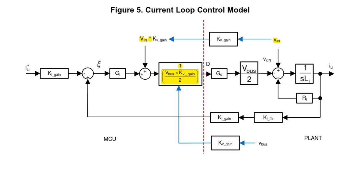
TIDM-1000: reference design PFC current loop block diagram

Part Number: TIDM-1000

HI Expert,

I am evaluating the TIDM-1000 reference design and trying to understand the PFC current loop. can you please explain a little more on the input blocks highlighted in yellow in the attached block diagram? i understood one of those must be the input voltage feed forward, but where is the gain for this feed forward? and what are the purpose of other highlighted blocks?

thanks,

Sam

  • Sam,

    I will give you a reply by the end of this week.

    Regards,

    Chen

  • Hi Chen,

    I was wondering if you had a chance to look at this.

    Also a new question-where in the 3phase Vienna software are the switching PWM signals set? i.e., from compensation loops to the PWM output configuration (initialization and dynamic duty cycle updating). I just need to understand how the digital loops are implemented. it would be helpful if you could point to me which files (c, assembly, header, etc.) in the project take care of this part of function.

    thanks,

    Sam

  • Sam,

    To answer your last question first:

    You can refer to page 23~24 of user guide which explains the software configuration. For PWM settings, it should be inside Vienna_hal.h and  Vienna_hal.c  file. You can also check the code inside ISR in vienna.h.

    Regards,

    Chen

  • I am evaluating the TIDM-1000 reference design and trying to understand the PFC current loop. can you please explain a little more on the input blocks highlighted in yellow in the attached block diagram? i understood one of those must be the input voltage feed forward, but where is the gain for this feed forward? and what are the purpose of other highlighted blocks?

    Hi,

    The upper one is the Vin feedforward. Kvin_gain is the feedforward gain.

    The middle one is the Vbus feedforward component. 

    This feedforward control is used to simplify the current loop plant model to be independent with Vin and Vbus.

    For more details, you can refer to the papers below

    https://ieeexplore.ieee.org/stamp/stamp.jsp?tp=&arnumber=1391098

    Regards,

    Chen