This thread has been locked.
If you have a related question, please click the "Ask a related question" button in the top right corner. The newly created question will be automatically linked to this question.
Tool/software: Code Composer Studio
Hello,
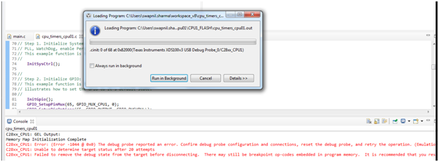
I am not able to load TI example program into TMS320F28075 using XDS100V3 debugger .
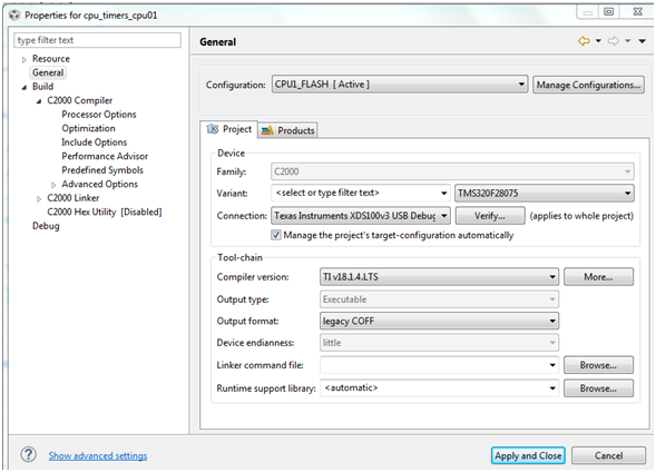
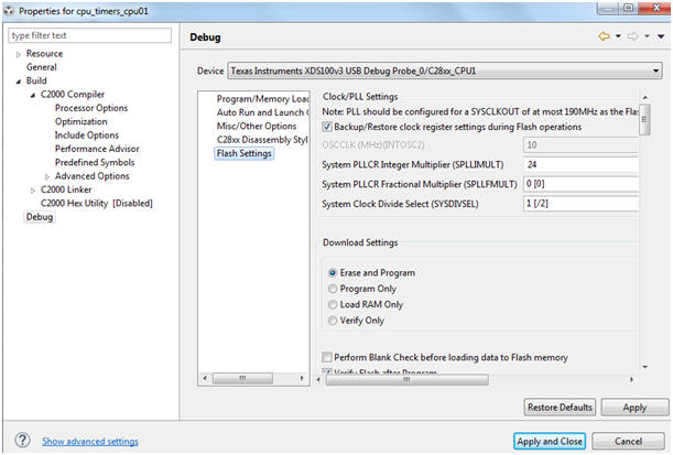
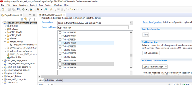
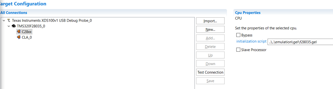
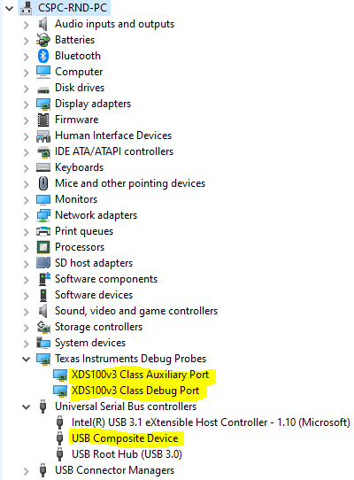
For your reference I am here sharing the screen shot of the error as well as CCS8.3.1 configuration settings.
Pl suggest what should I do to resolve this issue.
C28xx_CPU1: Error: (Error -1044 @ 0x0) The debug probe reported an error. Confirm debug probe configuration and connections, reset the debug probe, and retry the operation. (Emulation package 8.1.0.00012)
C28xx_CPU1: Trouble Halting Target CPU: (Error -1135 @ 0xC095) The debug probe reported an error. Confirm debug probe configuration and connections, reset the debug probe, and retry the operation. (Emulation package 8.1.0.00012)
C28xx_CPU1: Unable to determine target status after 20 attempts
C28xx_CPU1: Failed to remove the debug state from the target before disconnecting. There may still be breakpoint op-codes embedded in program memory. It is recommended that you reset the emulator before you connect and reload your program before you continue debugging.
Hi,
Images that you have uploaded are not visible. Whats the hardware that you are using ?
Hello,
I have our own designed pcb for TMS320F28075.
Pl find the images :
C28xx_CPU1: Error: (Error -1044 @ 0x0) The debug probe reported an error. Confirm debug probe configuration and connections, reset the debug probe, and retry the operation. (Emulation package 8.1.0.00012)
C28xx_CPU1: Trouble Halting Target CPU: (Error -1135 @ 0xC095) The debug probe reported an error. Confirm debug probe configuration and connections, reset the debug probe, and retry the operation. (Emulation package 8.1.0.00012)
C28xx_CPU1: Unable to determine target status after 20 attempts
C28xx_CPU1: Failed to remove the debug state from the target before disconnecting. There may still be breakpoint op-codes embedded in program memory. It is recommended that you reset the emulator before you connect and reload your program before you continue debugging
Hi,
SWAPNIL SHARMA said:I have our own designed pcb for TMS320F28075.
Are you using an external XDS probe then? What brand and version is it?
From the error messages, it looks like the MCU is either in reset, no powered, or not clocked. Have you verified reset, clock, and power on your board?
Hello,
Yes, I am using XDS100V3 of Olimex as an external debug probe.
The screenshot of configuration for this is shared below:
Pl find the JTAG pin connection status on our PCB:
TDI= 3.0 V
TDO= 3.0 V
TCK= 2.17 V
TMS= 3.0 V
TRST= 0.0 V (Normally) but after JTAG connectivity TRST goes high.
XRS pin status = High (Normally).....Initially after power on this pin goes low for few msec.
I am using 8MHz crystal on pin X1 & X2.
Hello,
I am using Test Connection button to verify that the JTAG connection is working.
Screenshot for the same is shared here to understand the issue which I am facing, I think this might be helpful :
[Start: Texas Instruments XDS100v3 USB Debug Probe_0]
Execute the command:
%ccs_base%/common/uscif/dbgjtag -f %boarddatafile% -rv -o -F inform,logfile=yes -S pathlength -S integrity
[Result]
-----[Print the board config pathname(s)]------------------------------------
C:\Users\swapnil\AppData\Local\TEXASI~1\
CCS\ccs1000\0\0\BrdDat\testBoard.dat
-----[Print the reset-command software log-file]-----------------------------
This utility has selected a 100- or 510-class product.
This utility will load the adapter 'jioserdesusbv3.dll'.
The library build date was 'Feb 13 2020'.
The library build time was '18:30:11'.
The library package version is '9.1.0.00001'.
The library component version is '35.35.0.0'.
The controller does not use a programmable FPGA.
The controller has a version number of '4' (0x00000004).
The controller has an insertion length of '0' (0x00000000).
This utility will attempt to reset the controller.
This utility has successfully reset the controller.
-----[Print the reset-command hardware log-file]-----------------------------
The scan-path will be reset by toggling the JTAG TRST signal.
The controller is the FTDI FT2232 with USB interface.
The link from controller to target is direct (without cable).
The software is configured for FTDI FT2232 features.
The controller cannot monitor the value on the EMU[0] pin.
The controller cannot monitor the value on the EMU[1] pin.
The controller cannot control the timing on output pins.
The controller cannot control the timing on input pins.
The scan-path link-delay has been set to exactly '0' (0x0000).
-----[The log-file for the JTAG TCLK output generated from the PLL]----------
Test Size Coord MHz Flag Result Description
~~~~ ~~~~ ~~~~~~~ ~~~~~~~~ ~~~~ ~~~~~~~~~~~ ~~~~~~~~~~~~~~~~~~~
1 64 - 01 00 500.0kHz O good value measure path length
2 64 + 00 00 1.000MHz [O] good value apply explicit tclk
There is no hardware for measuring the JTAG TCLK frequency.
In the scan-path tests:
The test length was 2048 bits.
The JTAG IR length was 6 bits.
The JTAG DR length was 1 bits.
The IR/DR scan-path tests used 2 frequencies.
The IR/DR scan-path tests used 500.0kHz as the initial frequency.
The IR/DR scan-path tests used 1.000MHz as the highest frequency.
The IR/DR scan-path tests used 1.000MHz as the final frequency.
-----[Measure the source and frequency of the final JTAG TCLKR input]--------
There is no hardware for measuring the JTAG TCLK frequency.
-----[Perform the standard path-length test on the JTAG IR and DR]-----------
This path-length test uses blocks of 64 32-bit words.
The test for the JTAG IR instruction path-length succeeded.
The JTAG IR instruction path-length is 6 bits.
The test for the JTAG DR bypass path-length succeeded.
The JTAG DR bypass path-length is 1 bits.
-----[Perform the Integrity scan-test on the JTAG IR]------------------------
This test will use blocks of 64 32-bit words.
This test will be applied just once.
Do a test using 0xFFFFFFFF.
Scan tests: 1, skipped: 0, failed: 0
Do a test using 0x00000000.
Scan tests: 2, skipped: 0, failed: 0
Do a test using 0xFE03E0E2.
Scan tests: 3, skipped: 0, failed: 0
Do a test using 0x01FC1F1D.
Scan tests: 4, skipped: 0, failed: 0
Do a test using 0x5533CCAA.
Scan tests: 5, skipped: 0, failed: 0
Do a test using 0xAACC3355.
Scan tests: 6, skipped: 0, failed: 0
All of the values were scanned correctly.
The JTAG IR Integrity scan-test has succeeded.
-----[Perform the Integrity scan-test on the JTAG DR]------------------------
This test will use blocks of 64 32-bit words.
This test will be applied just once.
Do a test using 0xFFFFFFFF.
Scan tests: 1, skipped: 0, failed: 0
Do a test using 0x00000000.
Scan tests: 2, skipped: 0, failed: 0
Do a test using 0xFE03E0E2.
Scan tests: 3, skipped: 0, failed: 0
Do a test using 0x01FC1F1D.
Scan tests: 4, skipped: 0, failed: 0
Do a test using 0x5533CCAA.
Scan tests: 5, skipped: 0, failed: 0
Do a test using 0xAACC3355.
Scan tests: 6, skipped: 0, failed: 0
All of the values were scanned correctly.
The JTAG DR Integrity scan-test has succeeded.
[End: Texas Instruments XDS100v3 USB Debug Probe_0]
Hi,
Thanks for the additional details, this helps narrow down the issue.
>> I am using 8MHz crystal on pin X1 & X2.
Per F28075 datasheet, the minimum support X1/X2 crystal frequency is 10MHz. This may not be the source of the problem, but it is a violation of the device spec. Can you confirm if the clock on X1 looks "ok"?
>> I am using Test Connection button to verify that the JTAG connection is working.
Thanks for sending this. I agree that the JTAG connection looks good.
Regarding the errors seen when you try to connect the device, these are generated when the GEL file tries to auto-execute some instructions. The ccxml file you created for your project will indicate which GEL script is being loaded. Can you share that information? See example below. You can get this information by opening the ccxml file in CCS and clicking the "Advanced" tab at the bottom.
Thank for sending the additional information. The gel file looks like it is the correct one for this device.
There is not much else to check other than the clock, power, and reset on the DSP itself. Can you verify the following on the DSP pins:
Are you using internal regulator (VREGENZ = 0)?
Hello Sir,
Thank you for your valuable reply.
Pl find the status of below pins:
VDDIO =3.3 V
VDD= 1.2 V
VDDA= 3.3 V
X1 clock frequency= 12MHz & voltage amplitude=2.5 V
XRSn= 3.3 V
& We are not using internal regulator so VREGENZ is tied to VDDIO= 3.3 V
Thanks for providing these additional details. Everything looks good there.
If we could take a more methodical approach to debugging this issue, there is a JTAG debug flow chart located here:
https://www.ti.com/lit/an/spracf0/spracf0.pdf
Could you review that flow chart? Some important questions/tips:
- Is there isolation implemented on your board? How is that isolation implemented.
- XRSn/TRSTn pull value & JTAG connector distance from DSP.
- Change boot mode to "wait boot".
- Use the "Connect Target" method (tip 10 on the list).
- Have you tried a second board?
Hello Sir,
Thank you for your suggestions.
>> Is there isolation implemented on your board? How is that isolation implemented.
Ans: We are using 5 V dc supply source in our board.
>> XRSn/TRSTn pull value & JTAG connector distance from DSP.
Ans: TRST pull down value is 2.2K ohm & on XRST pull value is 10 K ohm. JTAG connector distance from DSP is around 1 centimetre .
>> Change boot mode to "wait boot"
Ans: Yes, we changed boot mode to wait mode by pulling up GPIO72 & pulling down GPIO84.
>> Use the "Connect Target" method (tip 10 on the list)
Ans: Yes, we use connect target method mentioned in the spracf0 pdf .
>>Have you tried a second board?
Ans: No, right now we are having only one assembled board......assembly of second board is in progress .
Once 2nd board will be ready I'll try the same activity with it.
Hello Sir,
Thanks for your suggestion.
>> Is there isolation implemented on your board? How is that isolation implemented.
Ans: We are using 5V DC power supply for our board.
>>XRSn/TRSTn pull value & JTAG connector distance from DSP.
Ans: TRST is pull down by 2.2 Kohm & XRS is pull up through 10Kohm . JTAG connector distance from DSP is around 1 centimetre.
>> Change boot mode to "wait boot"
Ans: Yes, by pulling up GPIO72 & pulling down GPIO84 we changed to wait boot.
>> Use the "Connect Target" method (tip 10 on the list)
Ans: Yes, we use the "Connect Target" method given in spracf0 pdf .
>>Have you tried a second board?
Ans: No, right now we have only one assembled pcb. Second pcb assembly is in progress.
Once 2nd pcb will be assembled I'll try with that.
Still the same issue & error persists after doing all the above steps.
SWAPNIL SHARMA said:>> Is there isolation implemented on your board? How is that isolation implemented.
Ans: We are using 5V DC power supply for our board.
So there is no isolation implemented on your board, correct?
One more question, do you see the driver files for your debugger installed in Windows? See the "Present in Device Manager" step in the JTAG connectivity debug document (SPRACF0).
Can you also try to re-install CCS? Make sure to select all the Debug Probes when you get to that step in the CCS installation.
Hello sir,
>>So there is no isolation implemented on your board, correct?
Ans: In our board power supply isolation is implemented. Are you asking for some other isolation?
>> Are you tried with other board?
Ans: We tried with the second board , but the issue is still same.
>>One more question, do you see the driver files for your debugger installed in Windows? See the "Present in Device Manager" step in the JTAG connectivity debug document (SPRACF0).
Ans: Yes, we can. The screenshot of the same is attached here.
>> Can you also try to re-install CCS? Make sure to select all the Debug Probes when you get to that step in the CCS installation.
Ans: Yes, After doing the above steps this problem still persists.
Per off-line communication, the issue has been resolved. The problem was with the DSP going into reset during flashing/program execution due an issue with the on-board power supplies. With an external power supply powering the board, the DSP was successfully programmed.