


Tool/software: TI C/C++ Compiler
Hi Team,
Good day, we received query from our customer and and want to ask support about TMS320F28377D-EP. For me to not miss any information, Ill copy the query below.
"
I want to interface an SSI Sensor to the McBSP port of TMS320F28377D-EP.
I would to use the SN65HVD30MDREP to interface the MCU to the Sensor. Is it correct?
I would to use McBSP port in SPI mode (the other SPIs ports of the MCU are used for other peripherals) CLOCK signal is master from MCU (MCLKXx), while DATA are transmitted from Encoder to MCU (MDRx). Is it correct?
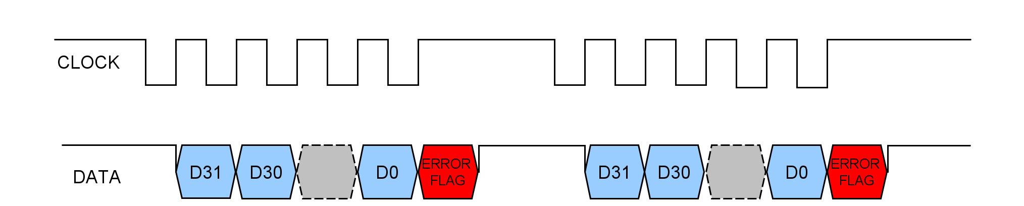
With reference to attached image, synchronous SSI uses a clock sequence from the MCU to initiate the transmission of data from the sensor (a Read Cycle).
Starting from t=0, after about 25 microseconds, the DATA line will be HIGH indicating a new Read Cycle can be started; at this point, the first falling edge starts the Read Cycle and the transfer of data.
Each rising edge of the CLOCK transmits the next data bit of the message, starting from D31 downto D0.
After the last rising edge of the clock sequence, the data line is set by the Error Flag.
I need to know if the McBSP port is correctly configured for my application (In this moment I cannot try it):
McbspaRegs.PCR.all=0x0F08;
McbspaRegs.SPCR1.bit.DLB = 0;
McbspaRegs.SPCR1.bit.CLKSTP = 2;
McbspaRegs.PCR.bit.CLKXP = 1;
McbspaRegs.PCR.bit.CLKRP = 0;
McbspaRegs.RCR2.bit.RDATDLY =01;
McbspaRegs.XCR2.bit.XDATDLY =01;
McbspaRegs.RCR1.bit.RWDLEN1 =32;
McbspaRegs.XCR1.bit.XWDLEN1 = 0;
McbspaRegs.SRGR2.all= 0x2000;
McbspaRegs.SRGR1.all= 0x0004;
McbspaRegs.SPCR2.bit.GRST=1;
McbspaRegs.SPCR2.bit.XRST=1;
McbspaRegs.SPCR1.bit.RRST=1;
McbspaRegs.SPCR2.bit.FRST=1;
I do not know how to handle the ERROR FLAG"
Thank you and looking forward for your kind response.
Regards,
Maynard
