This thread has been locked.

If you have a related question, please click the "Ask a related question" button in the top right corner. The newly created question will be automatically linked to this question.

CCS/TMS320F280049: TMS320F280049

Part Number: TMS320F280049
Other Parts Discussed in Thread: DAC108S085

Tool/software: Code Composer Studio

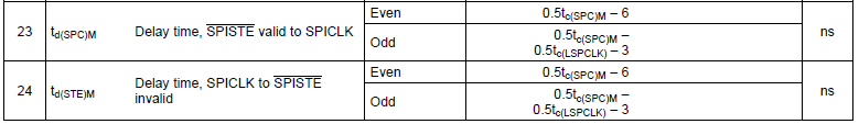
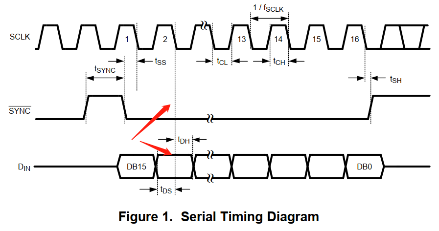
I have  a problem with the DAC108S085. The instruction manual said that the min value of tss is 3-10 ns, and the max value is (1/fSCLK - 3). I use TMS320F280049 to connect this DAC modular, but it's output parameter of tss cannot meet the requirement of the DAC chip. 

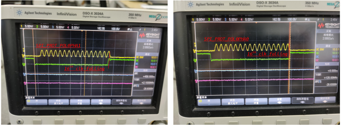
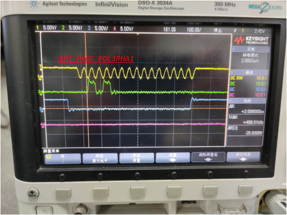
The output of the tms320f280049 is show below.

SCLK = 1MHz

according to the manual of DAC108S085:
max tss = 997ns
max tsh = 997ns

But in fact the output of TMS320F280049 is
tss = 2000ns
tsh = 480ns
the tss value cannot meet the requirement of DAC

I try to configure the output of the DSP, but I cannot find the way to configure this parameter of DSP

  • Hi,

    In the DAC datasheet, I see that "Once SYNC is low, the data on the DIN line is clocked into the 16-bit serial input register on the falling edges of SCLK". Looking at the snapshot you shared, it looks like the SPICLK is configured with Polarity = 0, in which the data is transmitted on the rising edge of SPICLK.

    Can you change the polarity and try?

    Regards

    Veena

  • Hi Veena,

    What you said is right, the picture i send is configure as rising edge of SPICLK, by configuring as 'SPI_PROT_POL0PHA0'

    I have try what you said by configuring as 'SPI_PROT_POL0PHA1', but the DAC still cannot be configure right. 

    Best regards.

    kevin

  • Hi Kevin,

    I believe the correct configuration should be : SPI_PROT_POL1PHA0.

    The information on delay time between STE active to SCLK and SCLK to STE inactive is mentioned in the datasheet. For 1MHz clock, the delay should be less than 500ns.

    Regards,

    Veena

  • the code is show below.

    void SPI_init() { //mySPI0 initialization // DAC108S085是在下降沿采集,也就是偶数沿,所以相位pha要设置成1,极性pol可以设置才0 //SIPBRR最小值是3 SPI_disableModule(mySPI0_BASE); SPI_setConfig(mySPI0_BASE, DEVICE_LSPCLK_FREQ, SPI_PROT_POL0PHA1, SPI_MODE_MASTER, 1000000, 16); SPI_disableFIFO(mySPI0_BASE); SPI_enableLoopback(mySPI0_BASE); SPI_setEmulationMode(mySPI0_BASE, SPI_EMULATION_STOP_AFTER_TRANSMIT); SPI_enableModule(mySPI0_BASE); } void SPI_transmit(uint32_t base, uint16_t sdata) { uint16_t rdata; SPI_writeDataNonBlocking(base, sdata);//Transmit data rdata = SPI_readDataBlockingNonFIFO(base);//Block until data is received and then return it if(rdata != sdata)//Check received data against sent data { //Something went wrong. rData doesn't contain expected data ESTOP0; } } void main() { uint16_t sData = 0; //Send data // // Initialize device clock and peripherals // Device_init(); // // Disable sync(Freeze clock to PWM as well) // SysCtl_disablePeripheral(SYSCTL_PERIPH_CLK_TBCLKSYNC); // Set up SPIs SPI_init(); // // Enable sync and clock to PWM // SysCtl_enablePeripheral(SYSCTL_PERIPH_CLK_TBCLKSYNC); EINT; ERTM; //SPI communication //设置寄存器为WTM模式 sData = 0X9000;//WRM:0X8xxx;WTM:0X9xxx; SPI_transmit(mySPI0_BASE, sData); while(1) { sData = 0X000;//设置A通道为full scall,高10位 SPI_transmit(mySPI0_BASE, sData); sData = 0X1800;//设置B通道为half scall,高10位 SPI_transmit(mySPI0_BASE, sData); sData = 0X2800;//设置C通道为1/4 scall,高10位 SPI_transmit(mySPI0_BASE, sData); sData = 0X3800;//设置D通道为full scall,高10位 SPI_transmit(mySPI0_BASE, sData); sData = 0X4800;//设置E通道为half scall,高10位 SPI_transmit(mySPI0_BASE, sData); sData = 0X5800;//设置F通道为1/4 scall,高10位 SPI_transmit(mySPI0_BASE, sData); sData = 0X6FFC;//设置G通道为half scall,高10位 SPI_transmit(mySPI0_BASE, sData); sData = 0X7FFC;//设置H通道为1/4 scall,高10位 SPI_transmit(mySPI0_BASE, sData); } }

  • Hi Veena,

    I have try the configuration of 'SPI_PROT_POL1PHA0', it fail also.

    Where are the picture you show? I find in the TMS320F28004X datasheet, and find that in the maste mode ,with high-speed, it's value is larger than what you show to me.

    and in non high-speed mode, it's value is shown below,

  • Hi Kevin,

    I am sorry, I was looking at an older version of the datasheet. As per the updated datasheet, for 1MHz clock, the STE active SCLK will be ~1400ns.

    Can you increase the SPICLK frequency and try?

    Regards,

    Veena

  • Hi Veena,

    I'm trying to increased the SPICLK frequency, but it seem that I should configure DSP as high-speed mode to increase the speed.

    I use the C2000 ware lib to program, can you tell me how to configure it as high-speed mode?

    Best regards

    Kevin

  • Hi Veena

    I just configured the SPICLK to 25MHZ, and the tss = 62ns, tsh=8ns. 

    But according to DAC108S085, tss should be 40ns,  it cannot meet the requirement of what it need.

     By the way, only when I set DSP as SPI_PROT_POL0PHA0, the 16th clk's fallinig edge be in the low range of sync signal.


  • Hi Kevin,

    But the DAC would be expecting the data on the falling edge of the SPICLK right? With SPI_PROT_POL0PHA0, the data will sent out on the rising edge.

    In case of SPI_PROT_POL0PHA0, there is half-cycle delay added to the normal SPI_PROT_POL0PHA0 behaviour.

    Regards,

    Veena

  • Hi Venna,

    Yes, I figure another graph under the condition of SPI_PROT_POL1PHA1, you can find that when on the falling edge, the valid data is not on the right position.

    This timing is not what the DAC need.

    Best regards

    Kevin

  • Hi Veena,

    I success to configure the DAC chip, by setting as ' SPI_PROT_POL0PHA0'.

    What i confuss is that, in this mode, it mean ' Rising edge without delay' for DSP, by the graph i catch seem to be 'Falling edge without delay'.

    You can see the difference of  SPI_PROT_POL0PHA0 and  SPI_PROT_POL1PHA0 in the picture below.

    Is it normal?

    Best regards

    Kevin

  • Hi Kevin,

    With polarity=0, data will be output on the rising edge of the SPICLK and with polarity=1, data will be output on the falling edge of the SPICLK.

    I am seeing the same behavior in the snapshot you shared.

    Regards,

    Veena

  • Hi,

    I haven’t heard from you for the last few weeks, so I’m assuming you were able to resolve your issue. If this isn’t the case, please reject this resolution and reply to this thread. If this thread locks, please click the "Ask a related question" button and in the new thread describe the current status of your issue and any additional details you may have to assist us in helping to solve your issues.

    Happy new year!

    Regards,

    Veena