Because of the Thanksgiving holiday in the U.S., TI E2E™ design support forum responses may be delayed from November 25 through December 2. Thank you for your patience.

This thread has been locked.

If you have a related question, please click the "Ask a related question" button in the top right corner. The newly created question will be automatically linked to this question.

LAUNCHXL-F28379D: Problem with EPWM

Part Number: LAUNCHXL-F28379D
Other Parts Discussed in Thread: C2000WARE

Hi,

Q1)

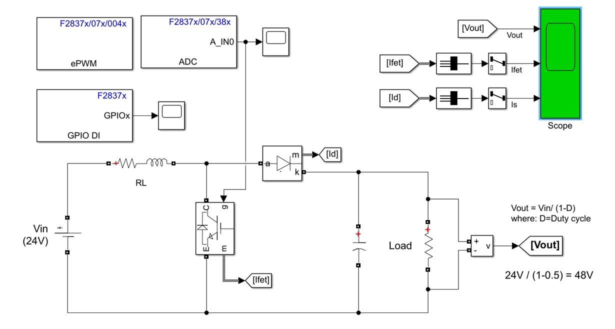
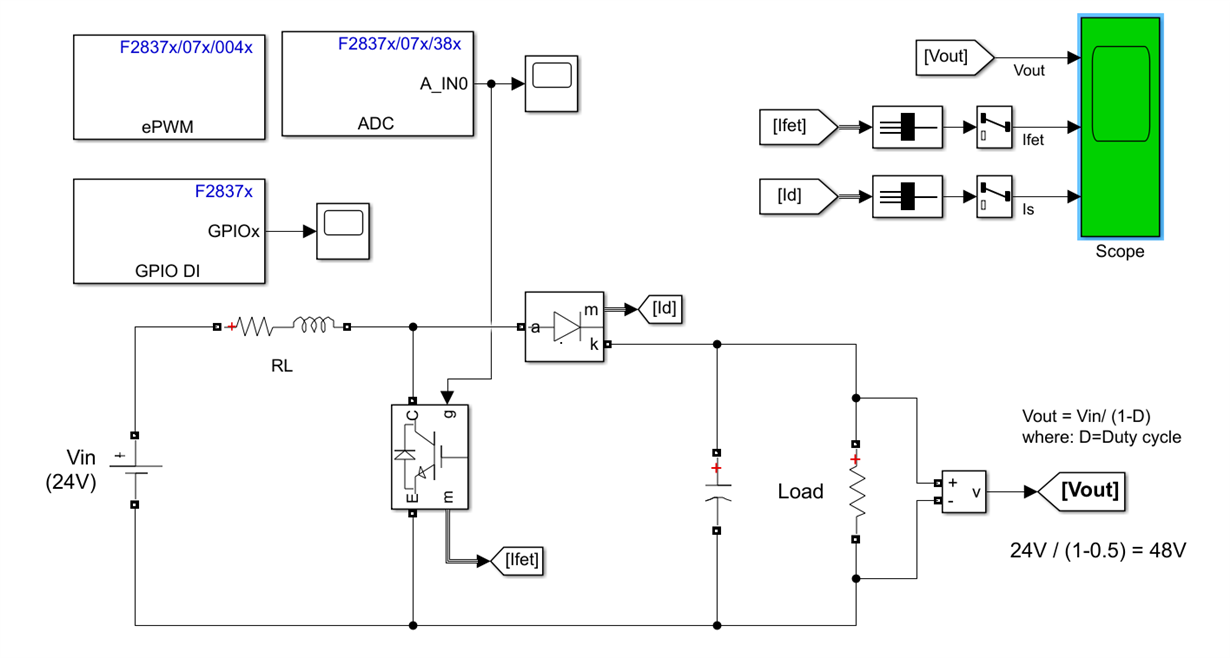
I modeled a boost converter in MATLAB and the simulation file works perfectly.

When I want to create a 20kHz PWM signal, the board cannot be able to generate even reasonable signals. For the timer period, I have used 5000, and for CMPA, I used 2500.

One time, I connected GPIO32 (pin 2) to pin 40 (epwmA) and one time, I connected pin 40 to ADCIN0 (pin30). None of them could be the solution. Surprisingly, the simulation starts from a time period far from 0 sec.

Do you know how this problem can be resolved?

Q2)

Now, there is another problem. When I connect the board to MATLAB or CCS, the Blue LED (R39) turns off. After flashing the board, it turns on after a few seconds of delay, and when I again, open MATLAB, the LED gets off. I don't know what is going on.

Thanks

  • Interestingly, while my board is connected to the computer and the driver is installed, MATLAB is saying, "Cannot start External mode simulation because target is not connected."

    How come?

  • Is your code able to run and are you able to debug when using CCS?

    Nima

  • Hi, Thanks for your reply.

    Right now, the board cannot be flashed. I checked the driver, I checked the USB cable, and I think, I have followed all the instructions but the Blue LED on the board turns off after a few seconds of connection to my computer.

  • Is the board detected by you PC?

  • Yes, both CPU1 and CPU2 can be detected.

    Even, after flashing, I can see 
    [12/14/2020, 12:12:05 PM] [SUCCESS] C28xx_CPU1: Operation completed successfully.
    [12/14/2020, 12:12:21 PM] [SUCCESS] C28xx_CPU2: Operation completed successfully.

    But, when I again disconnect the board, the Blue LED turns off. Sometimes, the RED one also turns off but almost all the time, the RED one is on.

    I think there should be a problem.

  • Which Blue and which red led are you referring to? D6 and D10?

  • D9 : RED : GPIO34 

    D10 : Blue : GPIO31 

  • Okay, Faisal can you post the error you get when you try to load the code through CCS?

    If the issue is that you dont actually get an error, and the CCS simply hangs please let me know.

    Nima

  • It seems that there is something wrong with CPU2 because when I try to load the program on CPU2 or flash CPU2, the Blue LED responds. Still, it is getting turn off for no reason. 

    There is no problem or error while loading the codes on the device through CCS.

  • Okay so I can assume that you are able to load and run code to CPU1 without issue. When loading code to CPU2, the LED changes state, thats all it just changes state?

    Nima

  • Normally, after erasing the board, three LEDs D1, D9, and D10 (in one row) should be on.

    If you see the two pictures, you can see that when I connected the board to the computer, only two LEDs get on, and after 2-3 minutes, the third LED (Blue one) switches on. This is abusively abnormal. This shouldn't be like that.

  • Do you use those GPIOs in your code?

  • Can you configure them as GPIO and pull them HIGH?

    Nima

  • Please check these videos.

    1- Red LED

    2- Blue LED

    3- Both LEDs

    4- After connecting the board to CCS to flash it (I have not performed flash, and just connected the board). What I expected was that the same as the past, three LEDs n the row turn on but as you can see only the green and red LEDs are on.

  • I think what is happening is that the GPIOs are configured by default as input. So the inputs are floating. These are connected to the LED driver circuitry and it randomly turns on/off. Please configure all three GPIOs to OUTPUT and pull them HIGH in the CPU1 code. Then they should not be affeceted by any external factors.

    Nima

  • There is no external factor over here. Nothing is connected to the board except for the USB cable.

    How should I do this? "Please configure all three GPIOs to OUTPUT and pull them HIGH in the CPU1 code."

  • I understand there is no "External factors" but when a GPIO is floating, and it is used an input to another circuit, then it can cause the other circuit to randomly get trigerred. Thats whats happening.

    Add the following lines of code to your driverlib project:

    	//GPIO34
    	GPIO_setPinConfig(GPIO_34_GPIO34);
            GPIO_setDirectionMode(34, GPIO_DIR_MODE_OUT);
    	GPIO_setPadConfig(34, GPIO_PIN_TYPE_STD);
    	GPIO_setMasterCore(34, GPIO_CORE_CPU1);
    	GPIO_setQualificationMode(34, GPIO_QUAL_SYNC);
    GPIO_writePin(34, 1);

    Thats for GPIO34. Do this for all of the LED GPIOs

  • I added the same codes that you provided and uploaded them to the board.

    The blue LED became on and after 5 seconds, again it turned off.

  • You configured your GPIO as output, when you set the pin high the LED should go OFF, are you sure you are downloading the code in there?

    Nima

  • Yes, sir. 100% sure.

  • My question is that why after flashing (let's say resetting both CPUs), the default configuration cannot be uploaded to the board? The default configurations say, after flashing the board, three LEDs should be on.

  • What do you mean by default configuration? IF you are flashing the board, the GPIOs driving those pins should 

    D1 is a connected to POWER. IT should always be ON when power is connected to the device.

    D9, D10 are connected to GPIO34 and GPIO31. If you want them to be a specific state, you MUST configure them. And if you do configure them, after the flashing of the device is compeleted, they will show the output of the program.

  • Please check this e2e URL.

    Kevin has mentioned:

    After erasing the F2837x device the LEDs D1, D9, & D10 should all stay lit when you plug the board in. Now you can re-program the device for running code out of flash or RAM.

    But I am doing exactly the same thing (100% the same) and this does not work for me and only LEDs D1 and D9 lit.

  •  can you comment on this?

  •  can you comment on this?

  • Faisal,

    When you erase the F28379D's flash and power cycle the board the GPIOs come up in a Hi-impedance state (i.e. they're floating). Based on that logic what I said earlier won't always be true. D9 and D10 may switch between on/off since the IOs they're driven by are floating.

    Best,

    Kevin

  • I understand what you are saying but let me explain.

    Let's say you connected the board, started CCS, flashed the board, based on your explanation either the LEDs should be on or off. Yes? My problem is that the LED is off but after 1-2 minutes, it turns on for no reason. Even, there is no program in it.

    Or it is on. It turns off unreasonably. All the time, the board is connected and no program (CCS or MATLAB is running). What is the problem?

    If you want, I can take a video and show how this is happening but what I have written is the true story. 

  • Faisal,

    Because GPIO 31 and 34 are left floating what you are witnessing is completely possible. The LED driver U9 on the board could see GPIO31/34 as HIGH or LOW at any time which can cause LEDs D9 and D10 to flicker like you're seeing. If you program the F28379D on-board and set GPIO31/34 as a steady HIGH or LOW output then the LEDs will not flicker.


    No need to provide a video, this is the explanation.

    Best,

    Kevin

  • Is there a default configuration that after resetting the board, the board follows a clear procedure and turn on D9 and D10 and keep them high? I am talking about resetting, not programming.

    Do you have any idea on the main problem that I have with epwm?

    LAUNCHXL-F28379D: Problem with EPWM - C2000™ microcontrollers forum - C2000™ microcontrollers - TI E2E support forums

  • Faisal,

    There is default software programmed into flash of the F2837x LaunchPad that will control the LEDs. If you've erased the flash of the device you can reprogram the SW found in C2000ware using CCS, directory location below:

    C:\ti\c2000\C2000Ware_3_03_00_00\device_support\f2837xd\examples\cpu1\launchxl_f28379d

    Faisal said:
    Do you have any idea on the main problem that I have with epwm?

    What is your original issue? I don't understand it from your first post.

    Best,

    Kevin

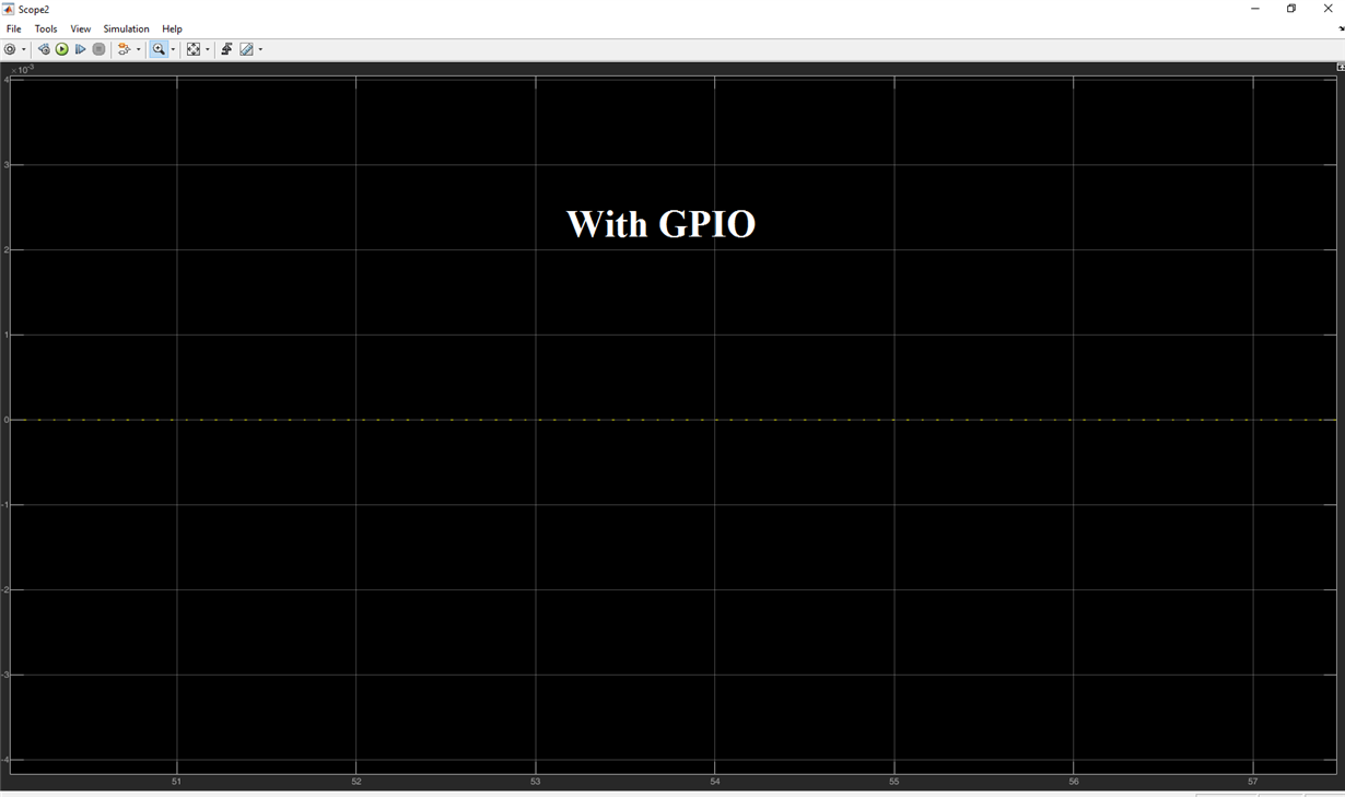
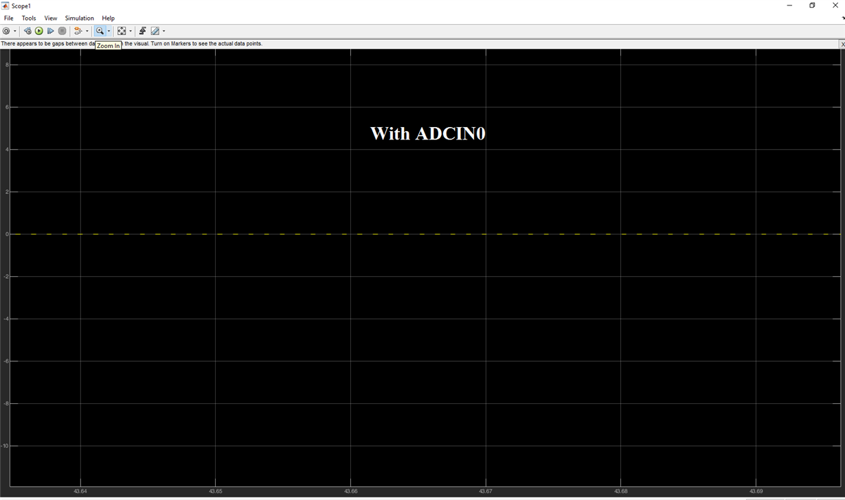
  • I simulated a buck converter in MATLAB and it was supposed that I get a 20 kHz signal either from GPIO or ADCIN because I connected the small wire from PIN40 (epwm1 pin) to PIN 2 (GPIO) or PIN 30 (ADCIN).

    As you can see, the frequency is zero and I cannot see anything on the scope.

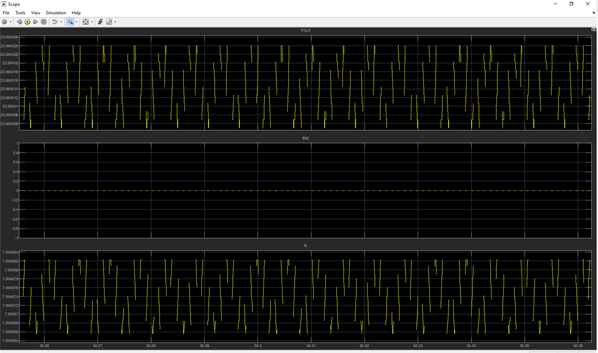
    The output of the circuit has been shown and you can see that instead of getting 48V output, I am getting something totally wrong. what is my mistake? This is not a difficult task to do and I am not sure whether I have done something wrong or the board is giving me the wrong output.

    By the way, I checked that path (mine is: C:\ti\c2000\C2000Ware_2_00_00_02\device_support\f2837xd\examples\cpu1\launchxl_f28379d) and still, I am unable to properly flash the board. The problem with flashing the board appeared exactly after simulating the above circuit. I also haven't configured anything from the above simulation to even toggle D9 and/or D10.

  • For your MATLAB generated code, please create a new thread state your issue with the Matlab code, please do not mention the LED issues so they dont assign you to an incorrect person. You need someone with knowledge of the MATLAB embedded coder to answer your question.

    In your title of your question make sure to mention MATLAB and embedded coder.

    Please close this thread and mark the solution to your LED problem.

    Nima

  • Nima

    The issue with the two LEDs has not been resolved yet.

  • Faisal,

    We have explained the LED behavior already. I'm not sure what else you want us to tell you.

    Please create a new E2E post for your Matlab related question so the correct expert can be notified and respond.

    Best,

    Kevin