This thread has been locked.

If you have a related question, please click the "Ask a related question" button in the top right corner. The newly created question will be automatically linked to this question.

TMS320F280049: The difference between two sets of CAN bit timing configurations

Part Number: TMS320F280049

Hi expert,

My customer is configurationg CAN on 100M F280049 device. There targeting baurd rate is 500k/bits.

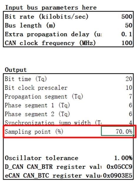
They get bit timing configuration from excel calculation sheet, result shown below:

Tseg1 = 13

Tseg2 = 6

SJW    = 4

BPR    = 10

Oscillator tolerance: df = 1.00%

They also worked out another set of configuration:

Tseg1 = 5

Tseg2 = 4

SJW    = 2

BPR    = 20

Oscillator tolerance: df = 1.587%

May I know if it will make a difference between these two?

How could I understand a Oscillator tolerance? How do I know how much it should be? (smaller the better?)

BTW, what is sampling rate here?

Thanks

Sheldon

  • Hi Sheldon,

    To make the CAN bit timing setup easier for the customer, this calculator was created and it only requires minimal input that is relevant to the customer, like the desired bit rate, CAN clock rate, the CAN bus length and the estimated propagation delay contributed by their choice of transceiver and associated circuits.  The calculator then outputs the values to in the format that is directly written to the CAN bit timing register and the allowable oscillator tolerance based on these 4 key inputs.

    The first configuration is obviously derived for 500kbps CAN bit rate, bus length of 50m, estimated extra propagation delay of 0.1us due to transceiver circuit design and assumed CAN clock rate of 100MHz.  Not sure about the second configuration, but I am assuming that customer may have chosen a different bus length, a different estimate for extra propagation delay, and maybe different CAN clock assumption.

    The oscillator tolerance reported by the calculator is a guidance on how far the clock on the F280049 device can deviate for the desired CAN bit rate.  For the case of the first configuration derived by the customer, it means that CAN clock will vary from 99MHz to 101Mhz and still transact CAN communications at 500kbps without errors on a 50m CAN bus.  If you try to input 1Mbps to the calculator without modifying the bus length and the extra prop delay, the reported oscillator tolerance drops down to 0.38% which is very tight (clock can only vary within 99.62MHz to 100.38MHz in order to attain 1Mbps CAN bit rate over 50m bus length).  Just provided these comparisons to illustrate the significance of oscillator tolerance in this text.  You can try experimenting with other values of bus length, CAN clock and CAN bit rate and see how the oscillator tolerance changes.

    The sampling point is where CAN senses the signal and decides if the value is dominant (0) or recessive (1).  For example, in the first configuration the sampling point reported is at 70%.  What this means is that the signal measurement point is at 70% of the bit width.  Bit width is simply the reciprocal of bit rate (1/500kbps), which is 2us.  For the first configuration, the sampling point is at 0.7*2uS, or 1.4uS.  You can refer to the bit timing figure in section 26.13.1 (Bit Time and Bit Rate) section of the TRM for an illustration on the sampling point and how the prop_seg, Tseg1 (phase_seg1) and Tseg2 (phase_seg2) reported by the bit timing calculator comes into play.

    Hope this helps and let me know if you still have questions on this topic.

    Best regards,

    Joseph 

  • Hi Joseph,

    Thanks for your explanation. Here are some related questions:

    1. Bit time can be divided into four parts, take that we received an "active" bit, will an "acive" voltage level be sampled by all these four parts?

    2. Based on question one, how will this bit be judged as valid? (how does it related to these four parts?)

    3. Is "Prop_Seg" configurable by registers? (In which register sets?)

    4. Based on question three, how do we calculate Prop_seg from resgister settings? 

    5. How do we decide a suitable sample point?

    Thanks

    Sheldon

  • Hi Sheldon,

    Bit timing is somewhat complicated part of the CAN protocol as it also involves synchronization of the nodes from phase errors caused by propagation delays.  The CAN bit timing calculator and app note simplifies bit timing for C2000 DCAN users.  You probably need to go through the CAN bit timing chapter in the TRM on Bosch CAN specification as well to get a full understanding of bit timing and synchronization.  Having stated that, I will attempt to answer below questions based on my understanding but please feel free to consult the TRM or Bosch CAN specification as well if responses below are not sufficient.

    1. Bit time can be divided into four parts, take that we received an "active" bit, will an "acive" voltage level be sampled by all these four parts?

    JC: Sampling is only done between Phase_seg1 and phase_seg2 and whatever the state of the signal is during the sampling point, that is the bit state that the CAN will report.  This is the simplified explanation, and if synchronization is needed, these phase segments can be lengthened or shortened by SJW.

    2. Based on question one, how will this bit be judged as valid? (how does it related to these four parts?)

    JC: The calculator defines these four parts based on CAN clock, desired bit rate, bus length and propagation delays.  It also determines the sampling point based on these inputs.  Whatever is the signal level read by the CAN at the sampling point will be the bit state interpreted by CAN.  It's not something that we can dictate.

    3. Is "Prop_Seg" configurable by registers? (In which register sets?)

    JC: This is part of field TSEG1 which is calculated in terms of tq (see TRM for definition).  TSEG1 consists of Prop_seg and Phase_seg1.  This is in CAN_BTR register. Prop_seg includes any delay time (hence calculator requires the length of the CAN bus as this is a big part of propagation delay).

    4. Based on question three, how do we calculate Prop_seg from resgister settings? 

    JC: Please refer to CAN bit timing calculator app note (SPRAC35).

    5. How do we decide a suitable sample point?

    JC: As stated earlier, this is set depending on CAN clock, desired bit rate, bus length and propagation delays.

    Best regards,

    Joseph