Other Parts Discussed in Thread: TMS320F28027, TMS320F28027F,
Hello everyone,
with Lori Heustess I managed to save program in flash either for non BIOS and BIOS projects (https://e2e.ti.com/support/microcontrollers/c2000/f/c2000-microcontrollers-forum/984757/launchxl-f28027f-can-t-boot-program-from-flash/36431100)
But now I have another odd problem. I wrote simple program in which there is an echo on UART. It works when I am debugging it by CCS but when I run it from flash only timer task works - I can see it by toggled LEDs. It seems that SCI interrupts are not fired. I put line that toggles LEDs in interrupt handlers and there was not any action. I have no idea what can cause that behaviour - as I wrote, timer handler works and LEDs are toggled in it. Here are files: main.c, app.cfg and TMS320F28027.cmd:
/*
* Copyright (c) 2015-2020, Texas Instruments Incorporated
* All rights reserved.
*
* Redistribution and use in source and binary forms, with or without
* modification, are permitted provided that the following conditions
* are met:
*
* * Redistributions of source code must retain the above copyright
* notice, this list of conditions and the following disclaimer.
*
* * Redistributions in binary form must reproduce the above copyright
* notice, this list of conditions and the following disclaimer in the
* documentation and/or other materials provided with the distribution.
*
* * Neither the name of Texas Instruments Incorporated nor the names of
* its contributors may be used to endorse or promote products derived
* from this software without specific prior written permission.
*
* THIS SOFTWARE IS PROVIDED BY THE COPYRIGHT HOLDERS AND CONTRIBUTORS "AS IS"
* AND ANY EXPRESS OR IMPLIED WARRANTIES, INCLUDING, BUT NOT LIMITED TO,
* THE IMPLIED WARRANTIES OF MERCHANTABILITY AND FITNESS FOR A PARTICULAR
* PURPOSE ARE DISCLAIMED. IN NO EVENT SHALL THE COPYRIGHT OWNER OR
* CONTRIBUTORS BE LIABLE FOR ANY DIRECT, INDIRECT, INCIDENTAL, SPECIAL,
* EXEMPLARY, OR CONSEQUENTIAL DAMAGES (INCLUDING, BUT NOT LIMITED TO,
* PROCUREMENT OF SUBSTITUTE GOODS OR SERVICES; LOSS OF USE, DATA, OR PROFITS;
* OR BUSINESS INTERRUPTION) HOWEVER CAUSED AND ON ANY THEORY OF LIABILITY,
* WHETHER IN CONTRACT, STRICT LIABILITY, OR TORT (INCLUDING NEGLIGENCE OR
* OTHERWISE) ARISING IN ANY WAY OUT OF THE USE OF THIS SOFTWARE,
* EVEN IF ADVISED OF THE POSSIBILITY OF SUCH DAMAGE.
*/
/*
* ======== TMS320F28027.cmd ========
* Define the memory block start/length for the F28027
*/
/*
* PAGE 0 will be used to organize program sections
* PAGE 1 will be used to organize data sections
*
* Notes:
* Memory blocks on F2802x are uniform (ie same
* physical memory) in both PAGE 0 and PAGE 1.
* That is the same memory region should not be
* defined for both PAGE 0 and PAGE 1.
* Doing so will result in corruption of program
* and/or data.
*
* L0 memory blocks are mirrored - that is
* they can be accessed in high memory or low memory.
* For simplicity only one instance is used in this
* linker file.
*/
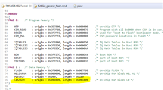
MEMORY
{
PAGE 0: /* Program Memory */
OTP : origin = 0x3D7800, length = 0x000400 /* on-chip OTP */
FLASH : origin = 0x3F0000, length = 0x007F80 /* on-chip FLASH */
CSM_RSVD : origin = 0x3F7F80, length = 0x000076 /* Program with all 0x0000 when CSM is in use. */
BEGIN : origin = 0x3F7FF6, length = 0x000002 /* Used for "boot to Flash" bootloader mode. */
CSM_PWL : origin = 0x3F7FF8, length = 0x000008 /* CSM password locations in FLASH */
IQTABLES : origin = 0x3FE000, length = 0x000B50 /* IQ Math Tables in Boot ROM */
IQTABLES2 : origin = 0x3FEB50, length = 0x00008C /* IQ Math Tables in Boot ROM */
IQTABLES3 : origin = 0x3FEBDC, length = 0x0000AA /* IQ Math Tables in Boot ROM */
ROM : origin = 0x3FF27C, length = 0x000D44 /* Boot ROM */
RESET : origin = 0x3FFFC0, length = 0x000002 /* part of boot ROM */
VECTORS : origin = 0x3FFFC2, length = 0x00003E /* part of boot ROM */
PAGE 1 : /* Data Memory */
M01SARAM : origin = 0x000000, length = 0x000800 /* on-chip RAM block M0, M1 */
PIEVECT : origin = 0xD00, length = 0x100
L0SARAM : origin = 0x008000, length = 0x001000 /* on-chip RAM block L0 */
}
/*
* Allocate sections to memory blocks.
* Note:
* codestart user defined section in DSP28_CodeStartBranch.asm
* used to redirect code execution when booting to flash
*
* ramfuncs user defined section to store functions that will be
* copied from Flash into RAM
*/
SECTIONS
{
/* Allocate program areas: */
.cinit : > FLASH PAGE = 0
.pinit : > FLASH PAGE = 0
.text : > FLASH PAGE = 0
codestart : > BEGIN PAGE = 0
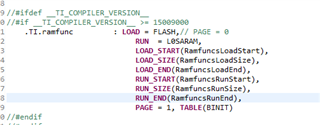
ramfuncs : LOAD = FLASH PAGE = 0,
RUN = L0SARAM PAGE = 1,
LOAD_START(_RamfuncsLoadStart),
LOAD_SIZE(_RamfuncsLoadSize),
LOAD_END(_RamfuncsLoadEnd),
RUN_START(_RamfuncsRunStart)
csmpasswds : > CSM_PWL PAGE = 0
csm_rsvd : > CSM_RSVD PAGE = 0
/* Allocate uninitalized data sections: */
.stack : > M01SARAM | L0SARAM PAGE = 1
.ebss : >> M01SARAM | L0SARAM PAGE = 1
.data : > M01SARAM | L0SARAM PAGE = 1
.esysmem : > L0SARAM | M01SARAM PAGE = 1
.cio : > L0SARAM | M01SARAM PAGE = 1
/* Initalized sections go in Flash */
/* For SDFlash to program these, they must be allocated to page 0 */
.econst : > FLASH PAGE = 0
.switch : > FLASH PAGE = 0
.args : > FLASH PAGE = 0
#ifdef __TI_COMPILER_VERSION__
#if __TI_COMPILER_VERSION__ >= 15009000
.TI.ramfunc : {} LOAD = FLASH PAGE = 0,
RUN = L0SARAM PAGE = 1,
table(BINIT)
#endif
#endif
/* Allocate IQ math areas: */
IQmath : > FLASH PAGE = 0 /* Math Code */
IQmathTables : > IQTABLES PAGE = 0, TYPE = NOLOAD
/*
* Uncomment the section below if calling the IQNexp() or IQexp()
* functions from the IQMath.lib library in order to utilize the
* relevant IQ Math table in Boot ROM (This saves space and Boot ROM
* is 1 wait-state). If this section is not uncommented, IQmathTables2
* will be loaded into other memory (SARAM, Flash, etc.) and will take
* up space, but 0 wait-state is possible.
*/
/*
IQmathTables2 : > IQTABLES2 PAGE = 0, TYPE = NOLOAD
{
IQmath.lib<IQNexpTable.obj> (IQmathTablesRam)
}
*/
/*
* Uncomment the section below if calling the IQNasin() or IQasin()
* functions from the IQMath.lib library in order to utilize the
* relevant IQ Math table in Boot ROM (This saves space and Boot ROM
* is 1 wait-state). If this section is not uncommented, IQmathTables2
* will be loaded into other memory (SARAM, Flash, etc.) and will take
* up space, but 0 wait-state is possible.
*/
/*
IQmathTables3 : > IQTABLES3 PAGE = 0, TYPE = NOLOAD
{
IQmath.lib<IQNasinTable.obj> (IQmathTablesRam)
}
*/
}
/*
* ======== main.c ========
*/
#include <xdc/std.h>
#include <xdc/runtime/Error.h>
#include <xdc/runtime/System.h>
#include <ti/sysbios/BIOS.h>
#include <ti/sysbios/knl/Task.h>
#include <ti/sysbios/hal/Hwi.h>
#include "DSP28x_Project.h" // Device Headerfile and Examples Include File
#include "adc.h"
#include "clk.h"
#include "flash.h"
#include "gpio.h"
#include "pie.h"
#include "pll.h"
#include "sci.h"
//#include "sci_io.h"
#include "timer.h"
#include "wdog.h"
#include "F2802x_SysCtrl.h" // System Control/Power Modes
//ADC_Handle myAdc;
CLK_Handle myClk;
//FLASH_Handle myFlash;
GPIO_Handle myGpio;
PIE_Handle myPie;
SCI_Handle mySci;
//TIMER_Handle myTimer;
/* Counter incremented by timer interrupt */
volatile UInt tickCount = 0;
volatile UInt txCount = 0;
uint16_t rxData = 0;
Void sciConfigTask(UArg a0, UArg a1);
Void gpioConfigTask(UArg arg, UArg a1);
Void sciTxIntFxn(UArg in);
uint16_t buffer[256] = {0};
/*
* ======== main ========
*/
Bits16 *OTP_KEY;
Bits16 *OTP_BMODE;
Int main()
{
#ifdef _FLASH
//memcpy(&RamfuncsRunStart, &RamfuncsLoadStart, (size_t)&RamfuncsLoadSize);
#endif
OTP_KEY = (Bits16*)0x3d7bfe;
OTP_BMODE = (Bits16*)0x3d7bff;
//CPU_Handle myCpu;
PLL_Handle myPll;
//WDOG_Handle myWDog;
//
// Initialize all the handles needed for this application
//
//myAdc = ADC_init((void *)ADC_BASE_ADDR, sizeof(ADC_Obj));
myClk = CLK_init((void *)CLK_BASE_ADDR, sizeof(CLK_Obj));
//myCpu = CPU_init((void *)NULL, sizeof(CPU_Obj));
//myFlash = FLASH_init((void *)FLASH_BASE_ADDR, sizeof(FLASH_Obj));
myGpio = GPIO_init((void *)GPIO_BASE_ADDR, sizeof(GPIO_Obj));
myPie = PIE_init((void *)PIE_BASE_ADDR, sizeof(PIE_Obj));
myPll = PLL_init((void *)PLL_BASE_ADDR, sizeof(PLL_Obj));
mySci = SCI_init((void *)SCIA_BASE_ADDR, sizeof(SCI_Obj));
//myTimer = TIMER_init((void *)TIMER0_BASE_ADDR, sizeof(TIMER_Obj));
//myWDog = WDOG_init((void *)WDOG_BASE_ADDR, sizeof(WDOG_Obj));
//
// Select the internal oscillator 1 as the clock source
//
CLK_setOscSrc(myClk, CLK_OscSrc_Internal);
//
// Setup the PLL for x12 /2 which will yield 60Mhz = 12Mhz * 10 / 2
//
PLL_setup(myPll, PLL_Multiplier_12, PLL_DivideSelect_ClkIn_by_2);
/*Task_Handle sciConfigTaskHandle;
Error_Block ebSci;
Error_init(&ebSci);
sciConfigTaskHandle = Task_create(sciConfigTask, NULL, &ebSci);
if (sciConfigTaskHandle == NULL) {
// System_printf("Task_create() failed!\n");
BIOS_exit(0);
}*/
/*Task_Handle gpioInitHandle;
Error_Block ebGpio;
Error_init(&ebGpio);
gpioInitHandle = Task_create(gpioConfigTask, NULL, &ebGpio);
if (gpioInitHandle == NULL) {
// System_printf("Task_create() failed!\n");
BIOS_exit(0);
}*/
/*Hwi_Handle sciTxIntHandle;
Error_Block ebSciTx;
Error_init(&ebSciTx);
sciTxIntHandle = Hwi_create(97, sciTxIntFxn, NULL, &ebSciTx);
if (sciTxIntHandle == NULL) {
// System_printf("Task_create() failed!\n");
BIOS_exit(0);
}
*/
//System_printf("BIOS start!");
BIOS_start(); /* does not return */
return(0);
}
Void gpioConfigTask(UArg arg, UArg a1){
//
// Configure GPIO 0-3 as outputs
// LEDs
//
GPIO_setMode(myGpio, GPIO_Number_0, GPIO_0_Mode_GeneralPurpose);
GPIO_setMode(myGpio, GPIO_Number_1, GPIO_0_Mode_GeneralPurpose);
GPIO_setMode(myGpio, GPIO_Number_2, GPIO_0_Mode_GeneralPurpose);
GPIO_setMode(myGpio, GPIO_Number_3, GPIO_0_Mode_GeneralPurpose);
GPIO_setDirection(myGpio, GPIO_Number_0, GPIO_Direction_Output);
GPIO_setDirection(myGpio, GPIO_Number_1, GPIO_Direction_Output);
GPIO_setDirection(myGpio, GPIO_Number_2, GPIO_Direction_Output);
GPIO_setDirection(myGpio, GPIO_Number_3, GPIO_Direction_Output);
GPIO_setLow(myGpio, GPIO_Number_0);
GPIO_setHigh(myGpio, GPIO_Number_1);
GPIO_setLow(myGpio, GPIO_Number_2);
GPIO_setHigh(myGpio, GPIO_Number_3);
}
/*
* ======== gpioToggle ========
* Timer ISR function that toggles GPIOs
*/
Void gpioToggle(UArg arg)
{
tickCount += 1; /* increment the counter */
//
// Toggle GPIOs
//
GPIO_toggle(myGpio, GPIO_Number_0);
GPIO_toggle(myGpio, GPIO_Number_1);
GPIO_toggle(myGpio, GPIO_Number_2);
GPIO_toggle(myGpio, GPIO_Number_3);
}
Void sciConfigTask(UArg a0, UArg a1){
//
// Initialize SCIA GPIO
//
GPIO_setPullUp(myGpio, GPIO_Number_28, GPIO_PullUp_Enable);
GPIO_setPullUp(myGpio, GPIO_Number_29, GPIO_PullUp_Disable);
GPIO_setQualification(myGpio, GPIO_Number_28, GPIO_Qual_ASync);
GPIO_setMode(myGpio, GPIO_Number_28, GPIO_28_Mode_SCIRXDA);
GPIO_setMode(myGpio, GPIO_Number_29, GPIO_29_Mode_SCITXDA);
CLK_enableSciaClock(myClk);
//
// 1 stop bit, No loopback, No parity, 8 char bits, async mode
// idle-line protocol
//
SCI_disableParity(mySci);
SCI_setNumStopBits(mySci, SCI_NumStopBits_One);
SCI_setCharLength(mySci, SCI_CharLength_8_Bits);
//
// enable TX, RX, internal SCICLK, Disable RX ERR, SLEEP, TXWAKE
//
SCI_enableTx(mySci);
SCI_enableRx(mySci);
SCI_enableTxInt(mySci);
SCI_enableRxInt(mySci);
//SCI_enableTxWake(mySci);
//SCI_enableLoopBack(mySci);
//SCI BRR = LSPCLK/(SCI BAUDx8) - 1
SCI_setBaudRate(mySci, SCI_BaudRate_9_6_kBaud);
//SCI_setBaudRate(mySci, SCI_BaudRate_9_6_kBaud);
#if (CPU_FRQ_50MHZ)
SCI_setBaudRate(mySci, SCI_BaudRate_9_6_kBaud);
#elif (CPU_FRQ_40MHZ)
SCI_setBaudRate(mySci, (SCI_BaudRate_e)129);
#endif
SCI_enable(mySci);
return;
}
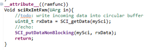
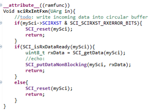
Void sciRxIntFxn(UArg in){
//GPIO_toggle(myGpio, GPIO_Number_0);
//todo: write incoming data into circular buffer
rxData = SCI_getData(mySci);
//echo:
SCI_putDataNonBlocking(mySci, rxData);
return;
}
Void sciTxIntFxn(UArg in){
//GPIO_toggle(myGpio, GPIO_Number_1);
//todo:
txCount++;
return;
}
Void idleFxn(){
return;
}
var Defaults = xdc.useModule('xdc.runtime.Defaults');
var Diags = xdc.useModule('xdc.runtime.Diags');
var Error = xdc.useModule('xdc.runtime.Error');
var Log = xdc.useModule('xdc.runtime.Log');
var Main = xdc.useModule('xdc.runtime.Main');
var Memory = xdc.useModule('xdc.runtime.Memory')
var SysMin = xdc.useModule('xdc.runtime.SysMin');
var System = xdc.useModule('xdc.runtime.System');
var Text = xdc.useModule('xdc.runtime.Text');

var BIOS = xdc.useModule('ti.sysbios.BIOS');
var Clock = xdc.useModule('ti.sysbios.knl.Clock');
var Swi = xdc.useModule('ti.sysbios.knl.Swi');
var Task = xdc.useModule('ti.sysbios.knl.Task');
var Semaphore = xdc.useModule('ti.sysbios.knl.Semaphore');

var Hwi = xdc.useModule('ti.sysbios.family.c28.Hwi');
var Timer = xdc.useModule('ti.sysbios.hal.Timer');
var ti_sysbios_hal_Hwi = xdc.useModule('ti.sysbios.hal.Hwi');
var Boot = xdc.useModule('ti.catalog.c2800.init.Boot');

/*
 * Uncomment this line to globally disable Asserts.
 * All modules inherit the default from the 'Defaults' module.  You
 * can override these defaults on a per-module basis using Module.common$.
 * Disabling Asserts will save code space and improve runtime performance.
Defaults.common$.diags_ASSERT = Diags.ALWAYS_OFF;
 */

/*
 * Uncomment this line to keep module names from being loaded on the target.
 * The module name strings are placed in the .const section. Setting this
 * parameter to false will save space in the .const section.  Error and
 * Assert messages will contain an "unknown module" prefix instead
 * of the actual module name.
Defaults.common$.namedModule = false;
 */

/*
 * Minimize exit handler array in System.  The System module includes
 * an array of functions that are registered with System_atexit() to be
 * called by System_exit().
 */
System.maxAtexitHandlers = 4;

/*
 * Uncomment this line to disable the Error print function.
 * We lose error information when this is disabled since the errors are
 * not printed.  Disabling the raiseHook will save some code space if
 * your app is not using System_printf() since the Error_print() function
 * calls System_printf().
Error.raiseHook = null;
 */

/*
 * Uncomment this line to keep Error, Assert, and Log strings from being
 * loaded on the target.  These strings are placed in the .const section.
 * Setting this parameter to false will save space in the .const section.
 * Error, Assert and Log message will print raw ids and args instead of
 * a formatted message.
Text.isLoaded = false;
 */

/*
 * Uncomment this line to disable the output of characters by SysMin
 * when the program exits.  SysMin writes characters to a circular buffer.
 * This buffer can be viewed using the SysMin Output view in ROV.
SysMin.flushAtExit = false;
 */

/*
 * The BIOS module will create the default heap for the system.
 * Specify the size of this default heap.
 */
BIOS.heapSize = 0x800;

/*
 * Build a custom SYS/BIOS library from sources.
 */
BIOS.libType = BIOS.LibType_Custom;

/* System stack size (used by ISRs and Swis) */
Program.stack = 0x100;

/* Circular buffer size for System_printf() */
SysMin.bufSize = 0x200;

/*
 * Create and install logger for the whole system
 */
/*var loggerBufParams = new LoggerBuf.Params();
loggerBufParams.numEntries = 32;
var logger0 = LoggerBuf.create(loggerBufParams);
Defaults.common$.logger = logger0;
Main.common$.diags_INFO = Diags.ALWAYS_ON;*/

System.SupportProxy = SysMin;
var timer0Params = new Timer.Params();
timer0Params.instance.name = "null";
timer0Params.period = 500000;
var timer0 = Timer.create(null, "&gpioToggle", timer0Params);
Task.enableIdleTask = true;
var hwi0Params = new Hwi.Params();
hwi0Params.instance.name = "sciRxInt";
hwi0Params.enableAck = true;
Program.global.sciRxInt = Hwi.create(96, "&sciRxIntFxn", hwi0Params);
var hwi1Params = new Hwi.Params();
hwi1Params.instance.name = "sciTxInt";
Program.global.sciTxInt = Hwi.create(97, "&sciTxIntFxn", hwi1Params);
var task0Params = new Task.Params();
task0Params.instance.name = "gpioInit";
Program.global.gpioInit = Task.create("&gpioConfigTask", task0Params);
var task1Params = new Task.Params();
task1Params.instance.name = "sciConfig";
Program.global.sciConfig = Task.create("&sciConfigTask", task1Params);
Boot.bootFromFlash = true;
Boot.configurePll = false;
Boot.pllOSCCLK = 12;
BIOS.cpuFreq.lo = 60000000;
Boot.pllcrDIV = 10;
I appreciate any help.
BR,
Dawid.

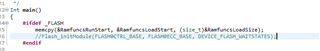

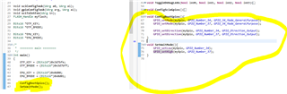
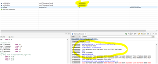
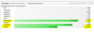
 we can see that functions are copied to L0SARAM