This thread has been locked.

If you have a related question, please click the "Ask a related question" button in the top right corner. The newly created question will be automatically linked to this question.

TMDSCNCD28379D: DAC not showing the correct signal; possible code overrun and how to solve it?

Part Number: TMDSCNCD28379D
Other Parts Discussed in Thread: TMDSCNCD28335,

Hi, I am experiencing a curious issue. I am using MATLAB Simulink 2018a for creating and loading the application code. Application code consists of ADC blocks, sinusoidal reference, control, PWM reference and PWM blocks (standard three-phase inverter closed-loop control)

There are four different cases, each with different results I have trouble explaining. In each case I monitor two signals on DAC (DACOUTA and DACOUTB): Ch1 is a sinusoidal reference and Ch4 is a space vector PWM reference.

  1. I load application code (Build, Load, Run and Boot from Flash (stand-alone)). Ch1 is a sinusoidal reference (50 Hz) and Ch4 is a space vector PWM reference (50 Hz) -> expacted results
  2. Same application code, but now in an External Mode: Ch1 is a sinusoidal reference (50 Hz) and Ch4 also a sinusoidal reference (50 Hz).
  3. I remove most of the code and keep only a sinusoidal reference and PWM reference calculation (open-loop control). I load application code (Build, Load, Run and Boot from Flash (stand-alone)). Ch1 is a sinusoidal reference (100 Hz) and Ch4 is a space vector PWM reference (100 Hz).
  4. Same simplified application code, but now in an External Mode: Ch1 is a sinusoidal reference (100 Hz) and Ch4 also sinusoidal reference (100 Hz)

Case 1 (Build, Load, Run) and 2 (External Mode):

Case 3 (Build, Load, Run) and 4 (External Mode):

Not sure why DACOUTB (Ch4) is showing different result for cases 1 and 2; can this mean the code for space vector reference is not executing?

Also, why is there a difference between case 1 and 3 when the waveform frequency increases from 50 Hz to 100 Hz? Does this mean all the code is executing slower in the former cases (case 1 and 2) .. which I could live with if I knew the fundamental and any other sample time is 2x higher for the 'bigger' code?

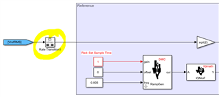
I had a similar issue with TMDSCNCD28335 and asked the question in the MATLAB forum where they suggested it might be due to overrun and I should optimise the sinusoidal reference block generation. So I moved to TMDSCNCD28379D, split the code between two CPUs and implemented a new sinusoidal reference calculation: now I am using optimised C28x DMC and IQmath block in the code and generate only ramp (0 - 2pi, 20 ms) and by using inverse Park transformation (Vd is set to 1, Vq and V0 are set to 0) I calculate three-phase sinusoidal reference.

Update:

Different waveform issue resolved.

In the space vector waveform calculation block I had several Simulink switches in the code, so it seems they stayed in a different position when the External Mode was running compared to the standard Build, Load and Run option. The zero-sequence waveform was not being injected into sinusoidal reference, hence the same waveform. Now I removed switches and the waveforms are as expected... It seems there is a problem with the switch block!

The frequency difference is still present.

  • Mike,

    Thanks for reaching out to the C2000 E2E. 

    One approach would be to back track this out of the C2000 register settings and confirm the differences in the PWM control register setting between case 1 and 3. 

    Since the frequency is double in case 3, maybe Simulink has added another Compare value to the PWM or changed from up count to up/down count or something like that.  It could be as simple as the period of the PWM halved.

    I think there is a way to get the generated C code out, we could examine that for differences between the two scenarios.  Hopefully we could tie this back to one of the configurations in the Simulink block.

    We could also connect CCS and examine the ePWM register settings that way as well.  Let me know what method you'd be most comfortable with and we can go from there.

    Best,
    Matthew

  • Hi Matthew,

    I have gone through the code (not an expert, hence using Simulink :) In both codes (Inverter_000_test.c and Inverter_001.c) ePWM is initialised the same:

    Fullscreen
    1
    2
    /*-- Setup Time-Base (TB) Submodule --*/
    EPwm5Regs.TBPRD = 12500; // Time Base Period Register
    XXXXXXXXXXXXXXXXXXXXXXXXXXXXXXXXXXXXXXXXXXXXXXXXXX

    A 'solution' (not sure if this is the correct one) for adjusting the output frequency is changing the 'Rate Transition' 'Output Port Sample Time' parameter from 10e-5 (smaller code Inverter_000_test) to 5e-5 (bigger code Inverter_001). Block name is 'Rate Transition1'.

    In Inverter_000_test.c and Inverter_001.c 'Rate Transition1' is defiend as

    Fullscreen
    1
    2
    3
    4
    5
    6
    /* RateTransition: '<Root>/Rate Transition1' */
    if (Inverter_001_M->Timing.RateInteraction.TID0_1) {
    Inverter_001_B.RateTransition1 = Inverter_001_DW.RateTransition1_Buffer0;
    }
    /* End of RateTransition: '<Root>/Rate Transition1' */
    XXXXXXXXXXXXXXXXXXXXXXXXXXXXXXXXXXXXXXXXXXXXXXXXXX

    In Inverter_001.c

    Fullscreen
    1
    2
    3
    4
    /* Update for RateTransition: '<Root>/Rate Transition1' incorporates:
    * Constant: '<Root>/Constant14'
    */
    Inverter_001_DW.RateTransition1_Buffer0 = Inverter_001_P.Constant14_Value_m;
    XXXXXXXXXXXXXXXXXXXXXXXXXXXXXXXXXXXXXXXXXXXXXXXXXX

    Fullscreen
    1
    2
    3
    4
    /* Computed Parameter: Constant14_Value_m
    * Referenced by: '<Root>/Constant14'
    */
    230.0F,
    XXXXXXXXXXXXXXXXXXXXXXXXXXXXXXXXXXXXXXXXXXXXXXXXXX

    In Inverter_000_test.c

    Fullscreen
    1
    2
    3
    4
    5
    6
    /* Update for RateTransition: '<Root>/Rate Transition1' incorporates:
    * Constant: '<Root>/Constant14'
    */
    Inverter_000_test_DW.RateTransition1_Buffer0 =
    Inverter_000_test_P.Constant14_Value_mo;
    }
    XXXXXXXXXXXXXXXXXXXXXXXXXXXXXXXXXXXXXXXXXXXXXXXXXX

    Fullscreen
    1
    2
    3
    4
    /* Computed Parameter: Constant14_Value_mo
    * Referenced by: '<Root>/Constant14'
    */
    230.0F
    XXXXXXXXXXXXXXXXXXXXXXXXXXXXXXXXXXXXXXXXXXXXXXXXXX

    So in both codes rate transition block constant is 230.0F... still have to investigate how this number is related to 5e-5.

    Please find attached the code for both cases. Sine waveform is sent to DACOUTA and DACOUTB.


    Inverter_000_test_ert_rtw.zip --> similified code, 100 Hz waveform

    Inverter_001_ert_rtw.zip --> more detailed code, 50 Hz waveform

  • Mike,

    Thanks for giving more background and sharing the simulink code. 

    I had mis-understood the initial tie in between the C2000 PWMs and the output DAC.  I had incorrectly assumed that the DAC updates were tied into the update rate/events of the C2000 PWMs itself, vs coming from a common update algorithm that feed both in parallel.  The PWM register settings likely have nothing to do with what we are seeing.

    I understand that you are using the DACs on the C2000 directly, fed from a Simulink calculated value(which does go to the C2000 PWMs, but unrelated to what you are measuring on your scope). 

    I think you are on the right track with the Rate Transition setting, as we are using the C28x CPU to manually write this value to the DAC Output register, the timing of the write is important to preserve the frequency.  I suspect when you slim down the code, the C28x has more CPU bandwidth to update the DAC blocks with the output from the Modulation 1 block.

    I see that the the output transition blocks that feed the DACs are controlled by a variable "Tcontrol" I would have thought this would keep the update rate constant between both versions of code. 

    It looks like this is used to control the update in the control block in Inverter_001 as well.  Not sure if making a distinct update control for the DACs would fix this when adding more code.

    I'm going to ask some of the folks at MW to comment a bit more here; if I were coding this in C I would likely tie the DAC update to one of the PWM ISRs to keep that update consistent with the PWM timebase itself; but with multiple update blocks perhaps these were all tied to a common CPU Timer, and its ISR.

    Best,

    Matthew

  • Hi Matthew -- I also recorded signals while running in External Mode. DAC and GPIO measure 50 Hz signals and logging signal gives 100 Hz waveform; same as with the 'smaller' code. PWM reference (control) signal is 50 Hz.

    PWM signal is the correct switching frequency (5 kHz). There are no additional update settings for DAC or GPIO. Setting DAC synchronization signal to e.g. PWMSYNC5 did not solve the problem. The signal is still 50 Hz but with a slightly smaller resolution.

    Does the signal frequency difference between the smaller and the bigger application code mean the code is too big and is overrunning?

  • Hi Mike,

    Can you provide your model files that are scale down version from the original model but still help us to reproduce the issue.

    Regards,

    Venkatesh C

  • Hi Venkatesh,

    yes, no problem. This is the layout of the smaller application code (file name: Inverter_000_test.slx); 100 Hz DAC output. The same elements are used in the bigger code (file name: Inverter_001.slx); 50 Hz DAC output

     ApplicationCodeF28379D.zip

  • Hi Mike,

    It is a model overrun condition that is causing this to happen. Basically the model Inverter_001.slx is overrunning the 50usec base task. If you put a GPIO toggle inside this model(top level of the model), the GPIO toggle would occur at the rate of 5KHz. So in the first 100usec the GPIO would go high and next 100usec it would go low. Hence in 200usec it would complete one cycle. Hence 5KHz. This means the model is getting refreshed every 100usec. As can be seen to complete generating 1 RAMP cycle, it takes 10msec assuming 50usec step time. This would generate a 100HZ DAC output. But if the model is overrunning, then to generate 1 RAMP cycle, it will take 20msec as we are now running at a step time of 100usec. Hence the 50Hz DAC output is generated.

    HTH,

    Regards,

    Venkatesh C

  • Hi Venkatesh,

    thank you very much. Toggling the signal at each step time helped a lot to pinpoint the issue. Even other tasks were overruning, i.e. step time was increased by 2. I have increased step time (for RAMP and ADC) and set them to be equal to control sample time (10 kHz) and now it works as expected.

    Off-topic: you maybe know of a more optimal way of implementing RAMP signal and generating sinusoidal reference?