This thread has been locked.

If you have a related question, please click the "Ask a related question" button in the top right corner. The newly created question will be automatically linked to this question.

TMS320F28388D: Boot pins not connected

Part Number: TMS320F28388D
Other Parts Discussed in Thread: UNIFLASH

Hello,

On my custom board with a F28388D device, I neglected to connect the default boot pins GPIO72 and GPIO84 to any pull-up/downs. GPIO72 is a no-connect on the board, while GPIO84 is connected to the EtherCAT PHY MII interface TX_ENA signal. When I boot my device without a debugger it does not run the code programmed in FLASH, which I believe can be expected with these signals not connected properly.

My question are

  1. Can I force a different set of pins for boot configuration
  2. OR, could I hard-code the boot code to boot from FLASH when there isn't a debugger connected?

Thanks!

  • Hi ,

    Can I force a different set of pins for boot configuration

    Yes, you can change the BOOTMODe pins by configuring the Zx_BOOTPINCONFIG location in USER OTP. Please refer section " 5.4.1 Configuring Boot Mode Pins for CPU1" in BOOTROM chapter of device TRM.

    OR, could I hard-code the boot code to boot from FLASH when there isn't a debugger connected?

    Yes, that is also possible by configuring 0 BOOTMODE pins. Please refer section "Zero Boot Mode Select Pins" in BOOTROM chapter of device TRM.

    Regards,

    Vivek Singh

  • Hi . Thank you for your prompt response. I believe this answers my questions but I have not had a chance to try either of your suggestions. When I do, and if I have any questions I'll come back to this thread. I'm marking as solved for now. Thanks!

  • Hello Vivek, do I need to write a custom application that utilizes the FlashAPI in order to program and User OTP? I'd prefer if I could write to User OTP in a debug session using Code Composer Studio, is that possible?

    Could you point me at some at any resources that could get me started in either?

  • Hi,

    Yes, you can use any flash programming tool (including CCS flash plug-in) to program the User OTP. In CCS, we have GUI option also where user can input the required value and program it. You can open the CCS Flash GUI by clicking on "Tools -> On-Chip Flash" in CCS after connecting to target.

    Regards,

    Vivek Singh

  • Hi thank you for your response.

    I'm trying the On-Chip Flash GUI in CCS and it looks like the OTP values are not getting programmed with the values I provide.

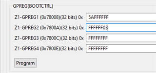
    These are the values I'm setting for Z1-GPREG1 and Z1-GPREG2 (Z1-BOOTPINCONFIG, Z1-BOOT-GPREG2)

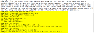
    Then after I hit "Program" the Console outputs prints what I highlighted in yellow here:

    However, reading back those registers with an expression watch returns all FFs

    Additionally, after I power cycle I still see all FFs in the expression watch and the device does not boot to Flash as would expect it to.

    I also verified that the values I provide for BootPinConfig (0x5AFFFFFF) and BootDef (0xFFFFFF03) are valid by using the Emulation approach, i.e. writing 0x5AFFFFFF to address 0x00000D00 (EMUBOOTPINCONFIG) and 0xFFFFFF03 to 0x00000D04 (EMUBOOTDEF-LOW).

    Any ideas why this isn't working?

  • I have noticed the following button on the GUI, what is the function of this button? Is it relevant here?

    "Security Settings" "All security values are located in One-time programmable (OTP) memory. Take caution prior to programming these values, as each bit can be programmed from 1 to 0 only once." Button reads: "Fill Security Fields from Target"

    I have also tried programming User OTP via firmware. Used the example in section 3 of this application report: https://www.ti.com/lit/an/spracp6/spracp6.pdf

    In my linker script, MEMORY section

    In the SECTIONS section:

    Then in main.cpp (C++ pragma)

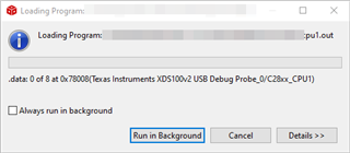
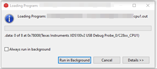
    Finally, why I try to load the .out file the loading gets stuck indefinitely writing to 0x78008 (DCSM OTP Zone 1 GPREG)

    Perhaps I'm not understanding how to lock/unlock DCSM? I thought the security module was unlocked from factory.

  • I have noticed the following button on the GUI, what is the function of this button? Is it relevant here?

    This icon is only provided to fill all the fields in the GUI by reading the value from device. It should not matter here. 

    Finally, why I try to load the .out file the loading gets stuck indefinitely writing to 0x78008 (DCSM OTP Zone 1 GPREG)

    Look like there is something missing in your CCS setup. Which version of CCS you are using ? Can you check for the updates and install new updates if there are any. You can find "Check for Update" icon under help menu in CCS.

    Regards,

    Vivek Singh

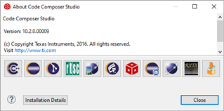
  • I'm using CCS 10.2.0

    I had the following version of the compiler tools prior to updating

    After running "Check for Updates" I installed these

    Then when I try to load the .out file it still gets stuck in the same place after erasing Flash

  • any idea why it's still getting stuck?

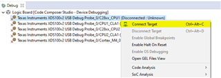
    For additional info on my setup, my Debug Configuration is not tied to any source project. After launching the debug configuration, I'm connecting to the target in the Debug Perspective with a right-click "Connect to Target"

    Then after it connects I load the .out file manually via the "Load Program" icon.

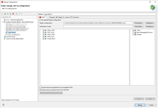
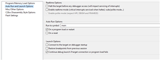
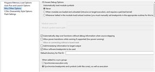
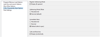
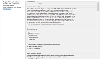
    Screenshots of the Debug Configuration settings are below:

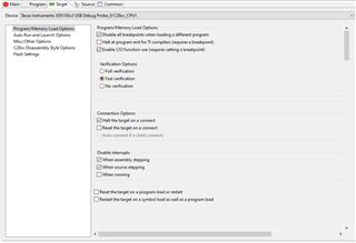
    And the "Target" tab

  • It look like you are following correct steps. Not sure why it is not working. Also there is no error message. Right ?

  • that's right, no error messages.

    Is it possible the DCSM is already locked for some reason? How could I tell if the DCSM is password locked?

  • In that case you should be getting error saying that zone is locked. When you open the GUI, do you see all the fields populated with proper value ?

  • I don't have the hardware with me today, but going off memory I recall seeing all FF's in all the fields in the GUI and clicking the " Fill Security Fields from Target" did not change them.

  • I looked at at your CCS window and it look a bit different. Which .ccxml file you are using for target configuration ? 

  • I'm using a .ccxml file that I grabbed from the CCS installation.

    Here are its contents

    <?xml version="1.0" encoding="UTF-8" standalone="no"?>
    <configurations XML_version="1.2" id="configurations_0">
    <configuration XML_version="1.2" id="Texas Instruments XDS100v2 USB Debug Probe_0">
            <instance XML_version="1.2" desc="Texas Instruments XDS100v2 USB Debug Probe_0" href="connections/TIXDS100v2_Connection.xml" id="Texas Instruments XDS100v2 USB Debug Probe_0" xml="TIXDS100v2_Connection.xml" xmlpath="connections"/>
            <connection XML_version="1.2" id="Texas Instruments XDS100v2 USB Debug Probe_0">
                <instance XML_version="1.2" href="drivers/tixds100v2icepick_c.xml" id="drivers" xml="tixds100v2icepick_c.xml" xmlpath="drivers"/>
                <instance XML_version="1.2" href="drivers/tixds100v2c28x.xml" id="drivers" xml="tixds100v2c28x.xml" xmlpath="drivers"/>
                <instance XML_version="1.2" href="drivers/tixds100v2cla2.xml" id="drivers" xml="tixds100v2cla2.xml" xmlpath="drivers"/>
                <instance XML_version="1.2" href="drivers/tixds100v2cs_child.xml" id="drivers" xml="tixds100v2cs_child.xml" xmlpath="drivers"/>
                <instance XML_version="1.2" href="drivers/tixds100v2cs_dap.xml" id="drivers" xml="tixds100v2cs_dap.xml" xmlpath="drivers"/>
                <instance XML_version="1.2" href="drivers/tixds100v2cortexM.xml" id="drivers" xml="tixds100v2cortexM.xml" xmlpath="drivers"/>
                <instance XML_version="1.2" href="drivers/tixds510ajsm.xml" id="drivers" xml="tixds510ajsm.xml" xmlpath="drivers"/>
                <platform XML_version="1.2" id="platform_0">
                    <instance XML_version="1.2" desc="TMS320F28388D_0" href="devices/f28388d.xml" id="TMS320F28388D_0" xml="f28388d.xml" xmlpath="devices"/>
                    <device HW_revision="1" XML_version="1.2" description="" id="TMS320F28388D_0" partnum="TMS320F28388D" simulation="no">
                        <router HW_revision="1.0" XML_version="1.2" description="ICEPick_C router" id="IcePick_C_0" isa="ICEPICK_C">
                            <subpath id="Subpath_1">
                                <property Type="numericfield" Value="0x11" desc="Port Number_0" id="Port Number"/>
                            </subpath>
                            <subpath id="CM">
                                <property Type="numericfield" Value="0x12" desc="Port Number_1" id="Port Number"/>
                            </subpath>
                        <subpath id="Subpath_3">
                                <cpu HW_revision="1.0" XML_version="1.2" description="JLM" deviceSim="false" id="JLM" isa="AJSM">
                                    <property Type="numericfield" Value="0x0" id="Unlock Key bits 31:00"/>
                                    <property Type="numericfield" Value="0x0" id="Unlock Key bits 63:32"/>
                                    <property Type="numericfield" Value="0x0" id="Unlock Key bits 95:64"/>
                                    <property Type="numericfield" Value="0x0" id="Unlock Key bits 127:96"/>
                                </cpu>
                            </subpath>
                        </router>
                    </device>
                </platform>
            </connection>
        </configuration>
    </configurations>

  • Jairo,

    Everything looks ok so it's strange that programming of the OTP fields are not happening. Have you tried a fresh device also ? 

    Vivek Singh

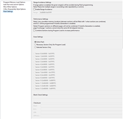
  • Hi , I'm happy to report that I was able to successfully program the OTP flash by using UniFlash on Windows (https://www.ti.com/tool/UNIFLASH). I tried two additional boards with CCS and was not successful there.

    The log output looks similar to the CCS output, but perhaps the gel (or other) script on UniFlash is more recent? This is what it looks like on UniFlash