This thread has been locked.

If you have a related question, please click the "Ask a related question" button in the top right corner. The newly created question will be automatically linked to this question.

TMS320F28377D: IDDK_PM_Servo_F2837x project (DACVALA)

Part Number: TMS320F28377D
Other Parts Discussed in Thread: CONTROLSUITE

Hello,

We purchased the DesignDRIVE Development Kit IDDK v2.2.1 and I have a question on the IDDK_PM_Servo_F2837x project.

It is stated in the file of IDDK_PM_Servo_F2837x.c as follows:

-------------------------------------------------------------------------------------------------------------

 //Enable DAC output
 DacaRegs.DACOUTEN.bit.DACOUTEN = 1;
 DacaRegs.DACCTL.bit.SYNCSEL    = 5;     // sync sel 5 meanse sync from pwm 6

-----------------------------------------------------------------------------------------------------------------

I suppose that the ePWM6SYNCO signal will update the DACVALA register according to C codes listed above.

It is also stated in the file of IDDK_PM_Servo_F2837x.c as follows:

------------------------------------------------------------------------------------------------------------------

 SyncSocRegs.SYNCSELECT.bit.EPWM4SYNCIN = 0;   //EPwm1SyncOut

 EPwm4Regs.TBCTL.bit.SYNCOSEL = TB_SYNC_IN;
 EPwm5Regs.TBCTL.bit.SYNCOSEL = TB_SYNC_IN;

 EPwm6Regs.TBCTL.bit.SYNCOSEL = TB_SYNC_IN;
 EPwm6Regs.TBCTL.bit.PHSEN    = TB_ENABLE;
 EPwm6Regs.TBPHS.bit.TBPHS    = 2;
 EPwm6Regs.TBCTL.bit.PHSDIR   = TB_UP;

---------------------------------------------------------------------------------------------------------------------

Then I suppose that the ePWM6SYNCO signal corresponds to the EPwm1SyncOut.

I assume that the EPwm1SyncOut means the ePWM1SYNCO signal.

It is stated in the function PWM_1ch_UpDwnCnt_CNF( ) of the file IDDK_PM_Servo_F2837x.c as follows:

------------------------------------------------------------------------------------------------------------------

 (*ePWM[n]).TBCTL.bit.SYNCOSEL = TB_CTR_ZERO; // sync "down-stream"

--------------------------------------------------------------------------------------------------------------------

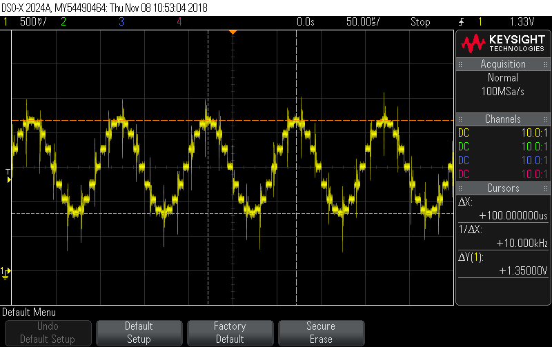
The time base counter (TBCTR) of the ePWM1 module may be cleared to zero at the period of INV_PWM_TICKS, which is 10,000 or 100us.

Therefore I suppose that the DACVALA register is to be updated every 100us.

Please review my reasoning on the update rate of the DACVALA register and point out where I have misunderstood it if I am wrong.

Thank you for your guidance.

G. Kim

  • Kim,

    At every SYNC input signal, the DACVALA content is updated with contents of DACVALS. Yes, in this case it is 100us.

    From your previous posts, we know that you are evaluating IDDK. If you read through the TRM, you will know the answers for most of the queries you have. Thanks.
  • Dear Ramesh,

    Thank you for your review.

    I need to discuss more on the update rate of the DACVALA register with you.

    It is stated in the file of resolver.c as follows:

    ----------------------------------------------------------------------------------------------------------------------------------------------------

    interrupt void ResolverISR ( void )
    {
        // *** Set up next sampling instant and update excitation sine wave ***
     rslvrOut.sineIndex = (rslvrOut.sineIndex-1) & (rslvrIn.TABLE_LENGTH-1);  // DELAY_LENGTH must be 2^n
     DacaRegs.DACVALS.bit.DACVALS = sineTable[rslvrOut.sineIndex];;

    -----------------------------------------------------------------------------------------------------------------------------------------------------

    The interrupt service routine ResolverISR() is executed at every 6.25us.

    I measured the resolver carrier signal on the IDDK main board.

    Its shape is a 10 kHz sine wave as shown in the captured display inserted below.

    The captured display inserted below shows one period of the 10 kHz carrier signal.

    The carrier signal is updated 16 times in one period of 100us.

    Therefore the carrier signal is updated at every 6.25us; it is updated at every execution of ResolverISR().

    Please comment on this issue for me.

    Thank you for your guidance.

    G. Kim

  • Hello,
    I remember typing the reply two weeks ago, but dont see it posted.

    Your observation is right. The sine wave carrier is generated by updating the sinewave over 16 instances within a 100us period, that is why you see 6.25us updates. You can refer to the resolver doc at
    C:\ti\controlSUITE\development_kits\TMDSRSLVR_v1.0\~Docs
  • Dear Ramesh,
    Thank you for your review.
    This issue has been resolved now.
    I now clearly understand the EPWMxSYNCO signal.
    I appreciate your guidance.
    With regards,
    G. Kim