This thread has been locked.

If you have a related question, please click the "Ask a related question" button in the top right corner. The newly created question will be automatically linked to this question.

DRV8301-69M-KIT: Understanding ADC operations in DRV8301 kit with TMS320F28069M controller

Part Number: DRV8301-69M-KIT
Other Parts Discussed in Thread: MOTORWARE

Hi,

I have a couple of queries regarding the ADCs. 

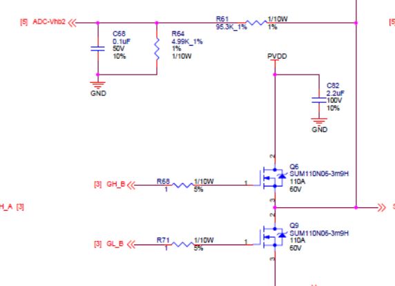
1. The voltage feedback is simply a resistor divider with a filter capacitor (sized for a particular cut-off frequency). What will be its effect on the input impedance of ADC? Will I have to change the acquisition time? Can you let me know what calculations should I perform so that the ADC S/H capacitor reaches within 0.5LSB margin?

2a. The HAL tutorial in the motorware project shows how to add an ADC for a potentiometer. It suggests triggering the ADC on ADCINT1. It mentions the end of conversion of channel 7 generates ADCINT1. Can you let me know which line of code does that? Also, which document describes the complete ADC sequence of operation for this application?

2b. I have a sin-cos encoder and I have to configure 2 ADC channels to it. I will be using it to calculate the angle and speed instead of the sensorless algorithm. Can you let me know when should I trigger these 2 ADCs and how important it is to trigger it with current ADCs? 

Thanks 

  • 2a. You can find the lines of code that setup the ADC interrupt source in HAL_setupAdcs(). The lines are

    // configure the interrupt sources
    ADC_disableInt(obj->adcHandle,ADC_IntNumber_1);
    ADC_setIntMode(obj->adcHandle,ADC_IntNumber_1,ADC_IntMode_ClearFlag);
    ADC_setIntSrc(obj->adcHandle,ADC_IntNumber_1,ADC_IntSrc_EOC7);

    and also in HAL_enableAdcInts(). The lines are

    // enable the PIE interrupts associated with the ADC interrupts
    PIE_enableAdcInt(obj->pieHandle,ADC_IntNumber_1);

    // enable the ADC interrupts
    ADC_enableInt(obj->adcHandle,ADC_IntNumber_1);

    // enable the cpu interrupt for ADC interrupts
    CPU_enableInt(obj->cpuHandle,CPU_IntNumber_10);

    2b. For sin-cos encoder, you can use a timer module to trigger the ADC interrupts, preferably at a high sampling rate. Since the feedback is continuous, you don't need to sync the sample window to something like a PWM trigger.
  • Hi Rushi,

    Your resistive impedance will be 4.99k || 95.3k = 4.74k and capacitance of 100nF

    First let's check how much settling you get from just the external capacitor:

    (1.6pF/100nF)*4096 = 0.06LSBs

    So you should be able to use a S+H window (controlled by ACQPS in the SOC configuration) near the minimum.

    However, in this case where all the external charge comes from the external cap ("charge sharing") we also need to ensure the external capacitor is adequately recharged in-between samples. Otherwise, the charge on the external capacitor will be depleted from subsequent samples (imagine the sample rate was very fast and the external R was infinite).

    So if we want 1/2LSBs of error, we roughly need the external 100nF capacitor to recharge from (Vin - 0.5LSBs) to (Vin - (0.5LSBs - 0.06LSBs)) in tsample, where tsample is the time between samples.

    tau = RC = 100nF*4.74k = 474us

    Time to charge to within a 0.5 LSB:
    -ln(0.5/4096)*tau

    Time to charge to within (0.5 - 0.06) LSB = 0.44LSBs:
    -ln(0.44/4096)*tau

    Time between samples =
    (ln(0.5/4096)-ln(0.44/4096))*tau = 60.6uS

    So if you want 1/2 LSBs of error, you should sample at 1/60.6uS = 16.5kHz or less.
    Note that this isn't the overall ADC sample rate, just how often this particular channel is sampled.

    If you need to sample faster, you can do some combination of
    (1) Accept additional error (maybe 1LSBs of error is OK for your application?)
    (2) Reduce the overall resistance of the voltage divider (and accept additional static current dissipation)

    Or you can add an op-amp buffer so that you don't have to rely on charge-sharing.
  • @Devin,

    It took some time to understand but your calculation is quite clear. Thanks. I have one doubt though. I think you have referred this figure when selecting the sampling capacitor as 1.6pF.

    I see Ron is equal to 3.4kOhms. Will it not affect the time? When the switch is closed, the 100nF comes in parallel with Cp and Ch with a time constant of approx 3.4k*100nF = 340us. So, it will take 340us to sample the ADC value? That is too long - probably I am making a mistake in calculations. Can you help me out? 

    @Sean 

    2a. No more doubts. Thanks

    2b. What does sampling at a higher rate imply? I can set a higher value of timer interrupt for ADC sampling. But then I need to read that value and perform the calculation for angle and speed. Where should I do that - in the mainISR() or main()? And if I do not calculate the angle at the same time the currents are sampled - will it not affect the DQ transformation accuracy? I need to understand this concept better. Please help. 


  • Hi Rushi,

    The external 100nF capacitor supplies all the charge in this case, so the time constant would just be 3.4kohm*1.6pF = 5.44ns.  For 1/2 LSBs settling you need ln(4096/0.5) = 9.01 time constants.  9.01*5.44ns = 49ns.  However, the minimum S+H time per the F2806x datasheet is 7 ADCCLKs * (1000/45MHz) = 156ns, so you'd just use that value (ACQPS = 6).

    If you had a smaller external capacitor (e.g. 220pF), you could use the following method to combine the external RC with the internal ADC RC (in this case you would not have any limitation on sample rate).  You would also probably need a smaller effective R from the voltage divider or would need to use an op-amp buffer.

  • The preferred method is to still tie the ADC SoC to the ePWM comparator to ensure a higher fidelity sample. I mention higher sampling rate just to improve the resolution of the feedback. Are you planning to use the QEP module as well? Typically, the scheme for sin-cos encoder is to use something like the comparator subsystem to detect a threshold of the input analog signal, and use the output of the comparator to A & B of the QEP module. You will also need to do this for I and feed it to the QEP. The QEP then gives the more coarse high byte of the angle value. You can use the ADC sample to provide a more fine reading (the lower byte) of the signal to interpret the angle, since QEP is typically only 10- or 11-bit resolution.

    Sean
  • Hi Devin,

    My query is solved and now I have a better understanding of these concepts. Thanks.

    Hi Sean,

    I do not intend to use QEP module. My sin-cos encoder sits on the shaft and I get only 1 complete sin/cos per revolution. In that case I think I have to rely on only the ADC and compue the speed and angle. Do you have a better suggestion/alernative?

    Thanks
  • You may use a CPU timer or EPWM timer to trig ADC to sample the output of Sin/Cos position sensor, and calculate the angle/position of rotor based the ADC sampling value every ISR if the Sin/Cos doesn't an embedded controller to convert its output to a digital value.