This thread has been locked.

If you have a related question, please click the "Ask a related question" button in the top right corner. The newly created question will be automatically linked to this question.

CCS/TMS320F280049: the problem on the ADC inside of F280049

Part Number: TMS320F280049
Other Parts Discussed in Thread: REF3025, ADS7947

Tool/software: Code Composer Studio

Dear colleagues

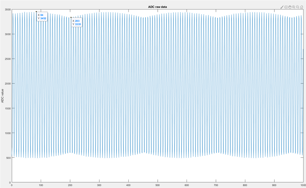
I used the ADC inside of F280049, I found one problem that the amplitude of signal would vary periodically.

So I do a test, To input a equal amplitude sine wave(50KHz, Vpp is about 0.5V~2V) to the pin A2 directly, and to use the oscilloscope to monitor this sine wave to make sure it is equal amplitude.

I used ADC inside of F280049 to sample(sampling rate is 400KHz, external reference ref3025), I got the result as below, the amplitude of sine wave vary periodically

If I used another equal amplitude non-sine wave to repeat this test,

I found the varying would become very much.

the case will not occur, when I use ADS7947 to repeat this test

Please help me to check this issue.

thanks!

br

jjl3


  • Hi,

    Refer the response from the below e2e query similar to this one.
    e2e.ti.com/.../2981547

    Thanks
    Vasudha
  • Hi jjl3,

    To add to the previous post, the pattern in the peaks is caused by the relative ratio of sampling frequency to input frequency.  You can verify that this is the case by changing the sampling or input frequency which will result in a new pattern and periodicity of peaks.  

  • Dear Cottier

    Thanks for your reply!

    after read through your previous post, I had some understanding.  

    but I still have a query of this phenomenon,

    as my understanding, the phenomenon occurred because of slight frequency difference, for example, the input frequency is actual 49.99KHz, sampling rate is 400KHz, then it will produce the slide. in fact, the root cause is these two frequency do not come from same one frequency source.

    In this case, the input frequency was produced by F280049 PWM, so I think both input frequency and ADC sampling frequency come from F280049 main clock(100MHz). so the slight frequency difference should not exist.

    I tried to add some value into 'Phase Active Reg' for ADC, actually no matter what value I add,  I can get almost equal amplitude waveform.

    so I still have a little confusion.

    thanks!

    BR

    jjl3

  • Hi jjl3,

    This sampling artifact occurs when the frequency of the input waveform is not an integer multiple of the sampling frequency. If both the input waveform and the sampling frequency are generated by the same device, probably the actual sampling frequency is not what you intended it to be (if you intended them to be integer multiples). You might want to use an oscilloscope to measure the input frequency and the sampling frequency directly.

    Note that I'm not sure that sampling a periodic signal exactly at an integer multiple of the input frequency is desirable. This will lead to different artifacts where the peaks could be missed since you sample at the same place each period.
  • thanks, again!