This thread has been locked.

If you have a related question, please click the "Ask a related question" button in the top right corner. The newly created question will be automatically linked to this question.

TMS320F28035: I need code for writing/reading to/from Microchip SRAM 23K256

Part Number: TMS320F28035

Does such code exist?

The same SPI is used for the flash and temperature reading and also the SRAM.

I have functions to read/write from/to the flash and the temperature - each needing a change of settings. CS is not enough.

I'm wondering if the SRAM will also need different settings before I can communicate with it.

Thanks,

Mechi

  • As an example - here's the code for initializing the SPIB:

    void init_spi(void)
    {
        Uint32 prodID = 0;
    
    	// SPIB
        // all SPIB CS are disabled
        GpioDataRegs.GPASET.bit.GPIO22 = 1;   // CS for MEMS
        GpioDataRegs.GPASET.bit.GPIO27 = 1;   // CS for temperature
        GpioDataRegs.GPASET.bit.GPIO23 = 1;   // CS for flash
        GpioDataRegs.GPASET.bit.GPIO10 = 1;   // CS for SRAM
    
        SpibRegs.SPICCR.all = 0x000F;                // Reset on, rising edge, 16-bit char bits
        SpibRegs.SPICTL.all = 0x000F;     // 0x0007 - for temperature     // Enable master mode, other clock phase,
                                                     // enable talk, and SPI INT enabled
    
        SpibRegs.SPIBRR = 0x007F;          // lowest Baud rate - divider - from 3 - 127
    
        SpibRegs.SPIPRI.all = 0x10;        //   FREE = 1, 4 wire SPI  // Set so breakpoints don't disturb xmission
    
        SpibRegs.SPIFFTX.all = 0xA040;    // FIFO not enabled
        SpibRegs.SPIFFRX.all = 0x2044;
        SpibRegs.SPIFFCT.all = 0x0;
    
        SpibRegs.SPICCR.bit.SPISWRESET = 1;    // // Relinquish SPI from Reset
    
        GpioDataRegs.GPASET.bit.GPIO4 = 1;   // disable Write protect for flash
        GpioDataRegs.GPASET.bit.GPIO5 = 1;   // disable HOLD for flash
    
        prodID = FlashReadManufacturer();
    
        if (prodID != 0x9D4013)   // id of flash
        {
            // error!
        }
    }

    When I read the temperature, not only do I set the CS, I also have to change the SPIB settings - 

    SpibRegs.SPICTL.all = 0x0007;   // for temperature

  • Mechi,

    Can you provide the PN for the SRAM chip you are using?  We don't have a library of drivers per se, but I can take a look at that device's datasheet to see if there is something very different than the other SPI interfaces that you have.

    Just to confirm, other than the change of SPICTL to 0007h for the temp sensor, all the other comms devices are working OK with the C2000 MCU?

    Best,

    Matthew

  • Data sheet attached.

    2 devices are working - flash and temperature.

    Here's the code in which I change the SPIB settings, start sensing temperature, and then when the temperature reading is stable, I reset the SPIB for the flash:

    	   if ((IsReadTemp == 1) && (SpibRegs.SPISTS.bit.INT_FLAG == 1 ))
    	   {
               wTemp = (int16_t)SpibRegs.SPIRXBUF;
               Temperature = ((float)(wTemp) * 0.0625L) / 8.0L;
    
               SpibRegs.SPICCR.all = 0x000F;                // Reset on, rising edge, 16-bit char bits
               SpibRegs.SPICTL.all = 0x000F;      //for flash    // Enable master mode, other clock phase,
                                                            // enable talk, and SPI INT enabled
               SpibRegs.SPICCR.bit.SPISWRESET = 1;    // // Relinquish SPI from Reset
    
    	       GpioDataRegs.GPASET.bit.GPIO27 = 1; // CS Disable for Temp
               IsReadTemp = 0;
    
               /* manipulates the heater according to the temperature */
               Operate_Heater(Temperature);
    	   }
    
    	   // can't read temperature if flash/SRAM is busy writing/reading
    	   if (!f_FlashBusy && !f_SRAM_busy && ((tsample - tQtemp) > 5000u))
    	   {
    	       IsReadTemp = 1;
    	       SpibRegs.SPICCR.all = 0x000F;        // Reset on, rising edge, 16-bit char bits
    	       SpibRegs.SPICTL.all = 0x0007;       // for temperature     // Enable master mode, other clock phase,
    	                                                    // enable talk, and SPI INT enabled
    	       SpibRegs.SPICCR.bit.SPISWRESET = 1;    // // Relinquish SPI from Reset
    
    	       // Start Read Temperature
                GpioDataRegs.GPACLEAR.bit.GPIO27 = 1;  // CS Enable
                SpibRegs.SPITXBUF = 0x01;
    
                tQtemp = tsample;
            }
    

    SRAM_22100F (256K).pdf

  • From code that I got from MicroChip site, the SPI is initialized as follows:

    config = SPI_CON_MSTEN | SPI_CON_MODE8 | SPI_SMP_OFF | SPI_CKE_ON | CLK_POL_ACTIVE_HIGH |SPI_CON_ON;    // SPI configuration word
    

    Now I have to translate to C2000

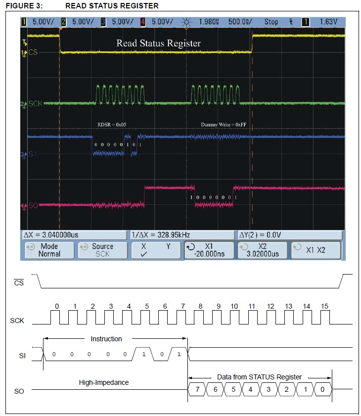
  • In the MicroChip doc, they show the following scope:

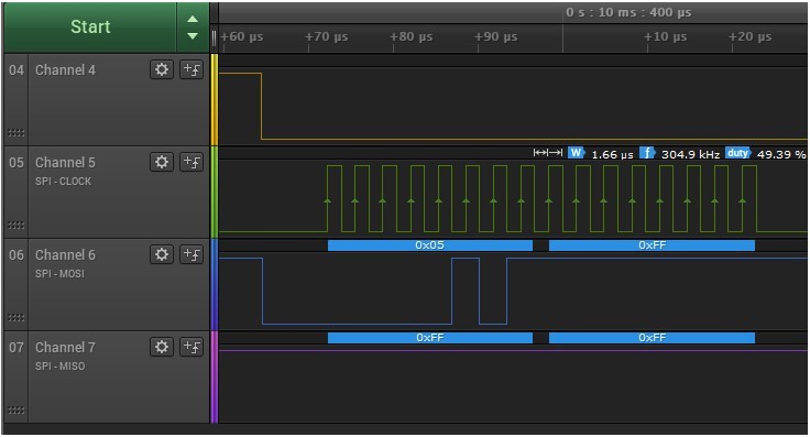
    With the C2000, I get the following - no answer from the chip:

  • From an initial read of the Microchip DS, the clock settings should be the same as the flash i.e. 

    SpibRegs.SPICTL.all = 0x000F;      //for flash    // Enable master mode, other clock phase,

    However, it looks like the RAM is expecting a character length of 8-bits vs the 16-bit setting, so you'll need to change the SPICRR to

    SpibRegs.SPICCR.all = 0x0007;                // Reset on, rising edge, 8-bit char bits

    The microchip DS is a bit ambiguous here, as the address length is 16-bits, but it looks like the instruction is only 8 bits long as well as the data out.  So for the address you'll need to have 2 8-bit X-fers with the MSBs(15-8) coming first the the LSB(7-0).

    Is the CS signal for the RAM coming from the native CS of the SPI module, or are you using a manual approach of a GPIO like the temp sensor?  Just want to make sure this is getting set active low correctly as well.

    Let's try  the above and see if this allows comms.

    Best,
    Matthew

  • Hi Matthew,

    Thanks so much for looking at the Datasheet for the SRAM. I'm using the driver with the 8-bit setting.

    I also spoke to some Microchip folks - they suggested to try to mimic the example shown in the Note (the screenshot of the scope shown above).

    This would mean sending the command (0x05) and then waiting (no clock) for a few microseconds, and only afterwards sending the dummy byte 0xFF for reading.

    How can this be accomplished if the RXBUF and TXBUF are both 16-bit?

    This is what I tried to do - but instead of writing 0x05, 0x0005 is written. And instead of 0xFF, 0x00FF is written. (see picture attached)

    And how do I make "quiet time" between the write and the read?

    Here's my code:

    #define SPI_TIMEOUT
    
    void init_spi(void)
    {  
    	// SPIB
        // all SPIB CS are disabled
        GpioDataRegs.GPASET.bit.GPIO22 = 1;   // CS for MEMS
        GpioDataRegs.GPASET.bit.GPIO27 = 1;   // CS for temperature
        GpioDataRegs.GPASET.bit.GPIO23 = 1;   // CS for flash
        GpioDataRegs.GPASET.bit.GPIO10 = 1;   // CS for SRAM
    
        SpibRegs.SPICCR.all = 0x0007;     // Reset on, rising edge, 8-bit char bits
    
        SpibRegs.SPICTL.all = 0x000F;     // 0x0007 - for temperature     // Enable master mode, other clock phase,
                                                     // enable talk, and SPI INT enabled
    
        //SpibRegs.SPIBRR = 0x007F;          // lowest Baud rate - divider - from 3 - 127  - 117kHz
        //SpibRegs.SPIBRR = 0x0030;          //   300kHz
        SpibRegs.SPIBRR = 0x0010;          //   900kHz
        //SpibRegs.SPIBRR = 0x008;          //   1.67MHz
    
        SpibRegs.SPIPRI.all = 0x10;        //   FREE = 1, 4 wire SPI  // Set so breakpoints don't disturb xmission
    
        SpibRegs.SPIFFTX.all = 0xA040;    // FIFO not enabled
        SpibRegs.SPIFFRX.all = 0x2044;
        SpibRegs.SPIFFCT.all = 0x0;
    
        SpibRegs.SPICCR.bit.SPISWRESET = 1;    // // Relinquish SPI from Reset
    }
    
    RET_STATUS_TYPE WaitUntilWordRcvd(void)
    {
        uint16_t j = 0u;
    
        // wait until new WORD arrives
        while((SpibRegs.SPISTS.bit.INT_FLAG !=1) && (j < SPI_TIMEOUT))
        {
            j++;
        }
    
        if (j >= SPI_TIMEOUT)
        {
            return RET_TIMEOUT;
        }
        else
        {
            return RET_OK;
        }
    }
    
    uint16_t SRAM_ReadStatusReg(void)
    {
        uint16_t  rxData = 0u;
        RET_STATUS_TYPE ret;
    
        GpioDataRegs.GPACLEAR.bit.GPIO10 = 1;   // CS for SRAM
    
    //    ret = WaitUntilBufEmpty();
    //    if (ret != RET_OK)
    //    {
    //        GpioDataRegs.GPASET.bit.GPIO10 = 1;   // CS for SRAM
    //        return ret;
    //    }
    
        SpibRegs.SPITXBUF = SRAM_RD_ST_REG;
    
        DSP28x_usDelay(100);
        ret = WaitUntilWordRcvd();
    
    //    if (ret == SPI_TIMEOUT)
    //    {
    //        GpioDataRegs.GPASET.bit.GPIO10 = 1;   // CS for SRAM
    //        return RET_TIMEOUT;
    //    }
    
        SpibRegs.SPITXBUF = 0xFF;   // from Arduino code
    
        rxData = SpibRegs.SPIRXBUF;  // get status register
    
        DSP28x_usDelay(400);
    
        GpioDataRegs.GPASET.bit.GPIO10 = 1;   // CS for SRAM
    
        return (rxData);  // returns WIP - Write In Process bit
    }

    I tried the code with the timeouts and waits (what's commented above) and without.

    No difference.

    I'd appreciate any help.

    Thanks,

    Mechi

  • To refine my question - if I use just one peripheral of 8 bits, I fill the TXBUF with the value shifted 8, and it shows as 8 bits.

    But can I change the SPI setup between peripherals in the code - one being 8 bits and one 16 bits?

    It's a bit tricky because the algorithm requires writing/reading to/from the flash at the same time as data is read/written /from/to the SRAM. Both are on the same SPI bus, but with different data sizes. Will this be very inefficient?

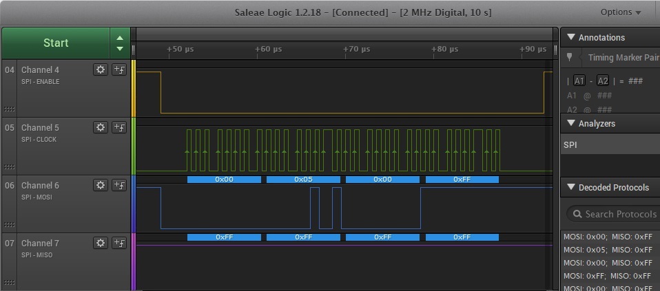
  •  Here's a screenshot using 8-bit data. I tried reading, writing and reading the status register. Still nothing on MISO

  • I found the answer - there is a HOLD bit that must be set HIGH all the time.

    We added a pull-up and enabled the pullup, but the pin had to be SET. once that was done, reading and writing are fine.