This thread has been locked.

If you have a related question, please click the "Ask a related question" button in the top right corner. The newly created question will be automatically linked to this question.

TMS320F28335: Remote frame debugging of CAN communication

Genius 3095 points
Part Number: TMS320F28335

Dear team:

One of my customers had some problems when using can communication module of f28335 and PC through can analyzer. The details are as follows:

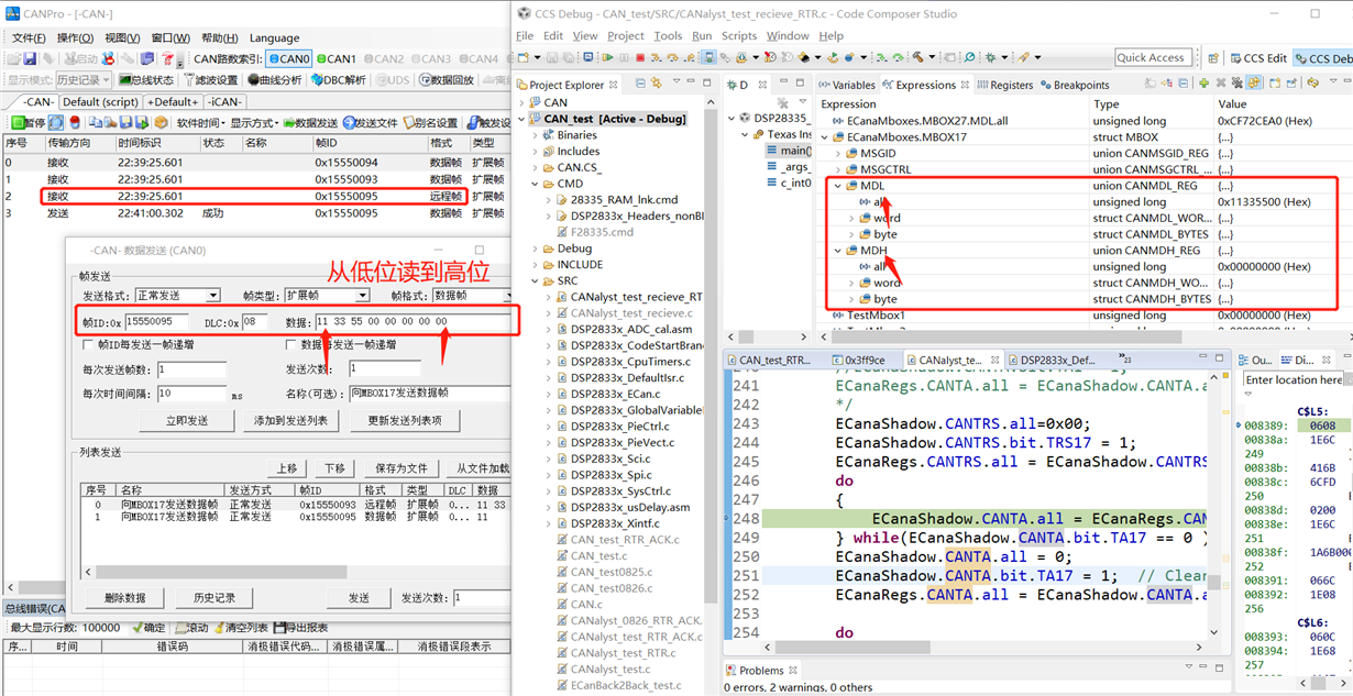
He configured the receiving mailbox of f28335 as the sender of remote frame, and set the corresponding RTR and TRS. However, the remote frame was successfully sent out only once in the test. As shown in Figure 1 (only this time is successful, and after that, no remote frame sent by DSP has been received).

The same code, then do the same experiment, remote frames can not be sent out. At the same time, no matter how the TRS and RTR are set, the bits read from the register are not set successfully according to the instruction, and are always kept at 0. The code is as follows:

Set ID:

Configure mailbox direction:

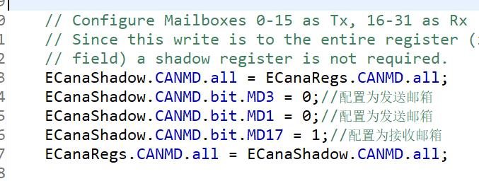
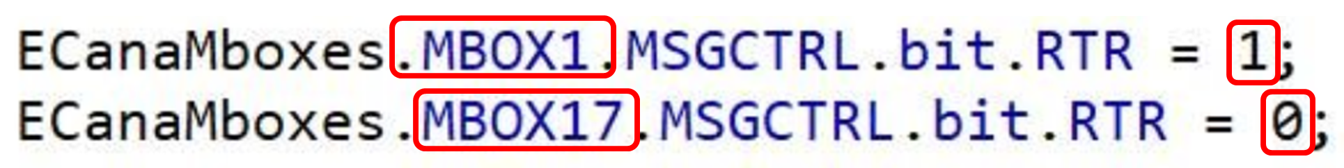
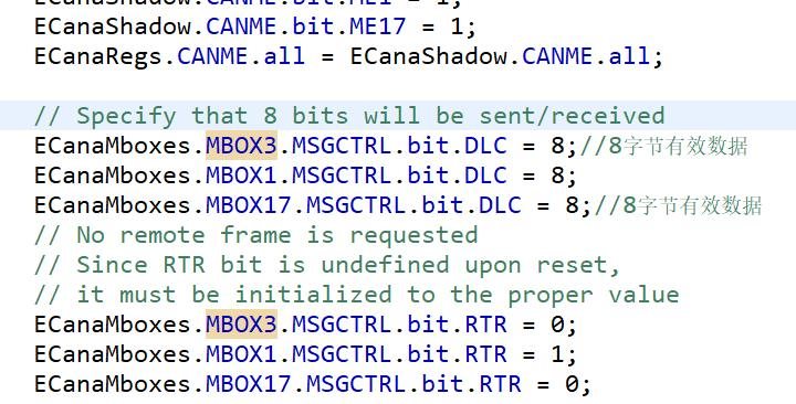
Enable mailbox, set DLC, RTR (from the register observation, it is found that these configurations failed)

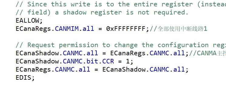
Other related configurations:

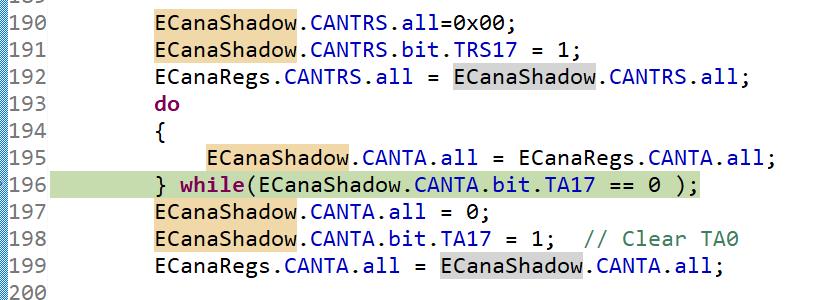
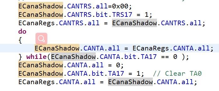
Set TRS (it will be stuck in the while loop, ta17 is always 0, trs17 and rtr17 are both 0, and remote frames sent are not monitored on the bus)

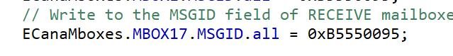
Msgid of receiving mailbox MBOX17 is set to B5550095 (AAM = 1, AME = 0)

Is there any problem with the above program configuration?

Best Regards

  • It appears MBOX17 is used to generate the remote frame. I see that it is configured as a receive MBX, by setting MD17 = 1. However, I notice that RTR bit is set for MBOX1 and RTR of MBOX17 is cleared to 0.


  • Sorry, I have cut a wrong picture. In fact, when I set the ECanaMboxes.MBOX17.MSGCTRL.bit.RTR as 1, I still can't recieve the remote frame from my CANalyst.

    I can only recieve the data frame from MBOX0&MBOX1, but the programme will be trapped in loop of 'ECanaShadow.CANTA.bit.TA17 == 0'.

    The frames that my CANanlyst recieved are as follow(Only data frame can be sent):

    My whole programme is as follow, thank you for your caring about my question. I am looking forward to your response! 

    #include "DSP2833x_Device.h"     // DSP2833x Headerfile Include File
    #include "DSP2833x_Examples.h"   // DSP2833x Examples Include File
    
    // Global variable for this example
    Uint32  MessageReceivedCount;
    
    void main(void)
    {
    // eCAN control registers require read/write access using 32-bits.  Thus we
    // will create a set of shadow registers for this example.  These shadow
    // registers will be used to make sure the access is 32-bits and not 16.
       struct ECAN_REGS ECanaShadow; 
    
    // Step 1. Initialize System Control:
    // PLL, WatchDog, enable Peripheral Clocks
    // This example function is found in the DSP2833x_SysCtrl.c file.
       InitSysCtrl();
    
    // Step 2. Initalize GPIO: 
    // This example function is found in the DSP2833x_Gpio.c file and
    // illustrates how to set the GPIO to it's default state.
    // InitGpio();  // Skipped for this example  
    
    // For this example, configure CAN pins using GPIO regs here
    // This function is found in DSP2833x_ECan.c
       InitECanGpio();
    
    // Step 3. Clear all interrupts and initialize PIE vector table:
    // Disable CPU interrupts 
       DINT;
    
    // Initialize PIE control registers to their default state.
    // The default state is all PIE interrupts disabled and flags
    // are cleared.  
    // This function is found in the DSP2833x_PieCtrl.c file.
       InitPieCtrl();
    
    // Disable CPU interrupts and clear all CPU interrupt flags:
       IER = 0x0000;
       IFR = 0x0000;
    
    // Initialize the PIE vector table with pointers to the shell Interrupt 
    // Service Routines (ISR).  
    // This will populate the entire table, even if the interrupt
    // is not used in this example.  This is useful for debug purposes.
    // The shell ISR routines are found in DSP2833x_DefaultIsr.c.
    // This function is found in DSP2833x_PieVect.c.
       InitPieVectTable();
    
    // Step 4. Initialize all the Device Peripherals:
    // This function is found in DSP2833x_InitPeripherals.c
    // InitPeripherals(); // Not required for this example
     
    // Step 5. User specific code, enable interrupts:
    
        MessageReceivedCount = 0;
        
        // eCAN control registers require 32-bit access. 
        // If you want to write to a single bit, the compiler may break this
        // access into a 16-bit access.  One solution, that is presented here,
        // is to use a shadow register to force the 32-bit access. 
         
        // Read the entire register into a shadow register.  This access
        // will be 32-bits.  Change the desired bit and copy the value back
        // to the eCAN register with a 32-bit write. 
       
        // Configure the eCAN RX and TX pins for eCAN transmissions
        EALLOW;
        ECanaShadow.CANTIOC.all = ECanaRegs.CANTIOC.all;
        ECanaShadow.CANTIOC.bit.TXFUNC = 1;
        ECanaRegs.CANTIOC.all = ECanaShadow.CANTIOC.all;
    
        ECanaShadow.CANRIOC.all = ECanaRegs.CANRIOC.all;
        ECanaShadow.CANRIOC.bit.RXFUNC = 1;
        ECanaRegs.CANRIOC.all = ECanaShadow.CANRIOC.all;
        EDIS;
         
        // Disable all Mailboxes
        // Since this write is to the entire register (instead of a bit
        // field) a shadow register is not required.
        ECanaRegs.CANME.all = 0;
    
        // Mailboxs can be written to 16-bits or 32-bits at a time
        // Write to the MSGID field of TRANSMIT mailboxes MBOX0 - 15 
        ECanaMboxes.MBOX0.MSGID.all = 0xB5550093;
        ECanaMboxes.MBOX1.MSGID.all = 0xB5550094;
        // Write to the MSGID field of RECEIVE mailboxes MBOX16 - 31
        ECanaMboxes.MBOX17.MSGID.all = 0xB5550095;
    
        // Configure Mailboxes 0-15 as Tx, 16-31 as Rx 
        // Since this write is to the entire register (instead of a bit
        // field) a shadow register is not required.
        ECanaShadow.CANMD.all = ECanaRegs.CANMD.all;
        ECanaShadow.CANMD.bit.MD0 = 0;
        ECanaShadow.CANMD.bit.MD1 = 0;
        ECanaShadow.CANMD.bit.MD17 = 1;
        ECanaRegs.CANMD.all = ECanaShadow.CANMD.all;
        
        // Enable all Mailboxes */
        // Since this write is to the entire register (instead of a bit
        // field) a shadow register is not required.
        ECanaShadow.CANME.all = ECanaRegs.CANME.all;
        ECanaShadow.CANME.bit.ME0 = 1;
        ECanaShadow.CANME.bit.ME1 = 1;
        ECanaShadow.CANME.bit.ME17 = 1;
        ECanaRegs.CANME.all = ECanaShadow.CANME.all;
    
        // Specify that 8 bits will be sent/received
        ECanaMboxes.MBOX0.MSGCTRL.bit.DLC = 8;
        ECanaMboxes.MBOX1.MSGCTRL.bit.DLC = 8;
        ECanaMboxes.MBOX17.MSGCTRL.bit.DLC = 8;
        // No remote frame is requested
        // Since RTR bit is undefined upon reset,
        // it must be initialized to the proper value 
        ECanaMboxes.MBOX0.MSGCTRL.bit.RTR = 0;
        ECanaMboxes.MBOX1.MSGCTRL.bit.RTR = 0;
        ECanaMboxes.MBOX17.MSGCTRL.bit.RTR = 1;
        // Write to the mailbox RAM field of MBOX0 - 15
        ECanaMboxes.MBOX0.MDL.all = 0xABCD6789;
        ECanaMboxes.MBOX0.MDH.all = 0x1234;
        ECanaMboxes.MBOX1.MDL.all = 0x6789;
        ECanaMboxes.MBOX1.MDH.all = 0x345678AB;
        // Since this write is to the entire register (instead of a bit
        // field) a shadow register is not required. 
        EALLOW;
        ECanaRegs.CANMIM.all = 0xFFFFFFFF;
    
        // Request permission to change the configuration registers
        ECanaShadow.CANMC.all = ECanaRegs.CANMC.all;
        ECanaShadow.CANMC.bit.CCR = 1;            
        ECanaRegs.CANMC.all = ECanaShadow.CANMC.all;
        EDIS;
        
        // Wait until the CPU has been granted permission to change the
        // configuration registers
        // Wait for CCE bit to be set..
        do 
        {
          ECanaShadow.CANES.all = ECanaRegs.CANES.all;
        } while(ECanaShadow.CANES.bit.CCE != 1 );  
        
        // Configure the eCAN timing
        EALLOW;
        ECanaShadow.CANBTC.all = ECanaRegs.CANBTC.all;
    
        ECanaShadow.CANBTC.bit.BRPREG = 9;    // (BRPREG + 1) = 10 feeds a 15 MHz CAN clock
        ECanaShadow.CANBTC.bit.TSEG2REG = 5 ; // to the CAN module. (150 / 10 = 15)
        ECanaShadow.CANBTC.bit.TSEG1REG = 7;  // Bit time = 15
        ECanaRegs.CANBTC.all = ECanaShadow.CANBTC.all;
        
        ECanaShadow.CANMC.all = ECanaRegs.CANMC.all;
        ECanaShadow.CANMC.bit.CCR = 0;            
        ECanaRegs.CANMC.all = ECanaShadow.CANMC.all;
        EDIS;
    
        // Wait until the CPU no longer has permission to change the
        // configuration registers
        do
        {
          ECanaShadow.CANES.all = ECanaRegs.CANES.all;
        } while(ECanaShadow.CANES.bit.CCE != 0 ); 
    
        // Configure the eCAN for self test mode 
        // Enable the enhanced features of the eCAN.
        EALLOW;
        ECanaShadow.CANMC.all = ECanaRegs.CANMC.all;
        ECanaShadow.CANMC.bit.STM = 0;    // Configure CAN for normal mode
        ECanaShadow.CANMC.bit.SCB = 1;    // eCAN mode (reqd to access 32 mailboxes)
        ECanaShadow.CANMC.bit.ABO = 1;    //auto bus on
        ECanaRegs.CANMC.all = ECanaShadow.CANMC.all;
        EDIS;
    
    
        // Begin transmitting 
        for(;;)                                
        {
        	ECanaShadow.CANTRS.all = 0;
        	ECanaShadow.CANTRS.bit.TRS1 = 1;
        	ECanaShadow.CANTRS.bit.TRS0 = 1;
        	ECanaRegs.CANTRS.all = ECanaShadow.CANTRS.all;
        	do
        	{
        		ECanaShadow.CANTA.all = ECanaRegs.CANTA.all;
        	} while(ECanaShadow.CANTA.bit.TA0 == 0 );
        	ECanaShadow.CANTA.all = 0;
        	ECanaShadow.CANTA.bit.TA0 = 1;  // Clear TA0
        	ECanaShadow.CANTA.bit.TA1 = 1;
        	ECanaRegs.CANTA.all = ECanaShadow.CANTA.all;
    
            ECanaShadow.CANTRS.all=0x00;
            ECanaShadow.CANTRS.bit.TRS17 = 1;
            ECanaRegs.CANTRS.all = ECanaShadow.CANTRS.all;
            do
            {
                ECanaShadow.CANTA.all = ECanaRegs.CANTA.all;
            } while(ECanaShadow.CANTA.bit.TA17 == 0 );
            ECanaShadow.CANTA.all = 0;
            ECanaShadow.CANTA.bit.TA17 = 1;  // Clear TA0
            ECanaRegs.CANTA.all = ECanaShadow.CANTA.all;
    
            do
        	{
        	   ECanaShadow.CANRMP.all = ECanaRegs.CANRMP.all;
        	} while(ECanaShadow.CANRMP.bit.RMP17 == 0 );
        	ECanaRegs.CANRMP.bit.RMP17 = 1;
        	MessageReceivedCount++;
        }
    }


  • So you don’t see a remote frame coming out of the 28x device even one time? Please download my Application report http://www.ti.com/lit/spra876. It has many tested examples. Specifically, look at this example: 

    • CAN_REMOTE_fr

    This example illustrates the ability of the CAN module to SEND remote frames from (and receive data

    frames in) the same Mailbox. 

    Try this example "as is". I also urge you to look at the Debug tips provided.

  • Thank you for your advice ! When I use 2 eCAN module from 2 DSP, I can send and recieve the remote frame successfully, using the example CAN_REMOTE_fr

    . But when I use eCANB, it can't both send and recieve. It seems that the eCANB have not been enabled. Can you give me some advice on how to enable the eCANB port? I have tried the programme as follow: (When I use eCANB in other project, it can't work either.)

    #include "DSP2833x_Device.h"     // DSP2833x Headerfile Include File
    #include "DSP2833x_Examples.h"   // DSP2833x Examples Include File
    
    void MBXwrA(void);                 // This function initializes all 32 MBOXes of CAN-A
    void MBXwrB(void);                 // This function initializes all 32 MBOXes of CAN-B
    
    main()
    {
    
    /* Create a shadow register structure for the CAN control registers. This is
     needed, since, only 32-bit access is allowed to these registers. 16-bit access
     to these registers could potentially corrupt the register contents. This is
     especially true while writing to a bit (or group of bits) among bits 16 - 31 */
    
    struct ECAN_REGS ECanaShadow;
    struct ECAN_REGS ECanbShadow;
    
    /* Kill Watchdog, Init PLL, Enable peripheral clocks */
    
    	InitSysCtrl();
    
    /* Initialize the CAN module */
    
    	InitECan();
    	InitECanGpio();
        // Configure the eCAN timing
        EALLOW;
         //CAN A
        ECanaShadow.CANBTC.all = ECanaRegs.CANBTC.all;
    
        ECanaShadow.CANBTC.bit.BRPREG = 9;    // (BRPREG + 1) = 10 feeds a 15 MHz CAN clock
        ECanaShadow.CANBTC.bit.TSEG2REG = 5 ; // to the CAN module. (150 / 10 = 15)
        ECanaShadow.CANBTC.bit.TSEG1REG = 7;  // Bit time = 15
        ECanaRegs.CANBTC.all = ECanaShadow.CANBTC.all;
    
        ECanaShadow.CANMC.all = ECanaRegs.CANMC.all;
        ECanaShadow.CANMC.bit.CCR = 0;
        ECanaRegs.CANMC.all = ECanaShadow.CANMC.all;
          //CAN B
        ECanbShadow.CANBTC.all = ECanbRegs.CANBTC.all;
    
        ECanbShadow.CANBTC.bit.BRPREG = 9;    // (BRPREG + 1) = 10 feeds a 15 MHz CAN clock
        ECanbShadow.CANBTC.bit.TSEG2REG = 5 ; // to the CAN module. (150 / 10 = 15)
        ECanbShadow.CANBTC.bit.TSEG1REG = 7;  // Bit time = 15
        ECanbRegs.CANBTC.all = ECanbShadow.CANBTC.all;
    
        ECanbShadow.CANMC.all = ECanbRegs.CANMC.all;
        ECanbShadow.CANMC.bit.CCR = 0;
        ECanbRegs.CANMC.all = ECanbShadow.CANMC.all;
        EDIS;
    
        // Wait until the CPU no longer has permission to change the
        // configuration registers
        do
        {
          ECanaShadow.CANES.all = ECanaRegs.CANES.all;
        } while(ECanaShadow.CANES.bit.CCE != 0 );
    
        do
        {
          ECanbShadow.CANES.all = ECanbRegs.CANES.all;
        } while(ECanbShadow.CANES.bit.CCE != 0 );
    
    	EALLOW;
    
    /* Zero out (or initialize) the entire MBX RAM area */
    
    	MBXwrA();//邮箱清零
    	MBXwrB();
    
    /* Write to the MSGID fields of both CAN-A & CAN-B  */
    
       	ECanaMboxes.MBOX2.MSGID.all  = 0x00080000;  // Standard identifier (Will be transmitted as a Remote frame)
        ECanaMboxes.MBOX3.MSGID.all  = 0x000C0000;  // Standard identifier (Will be transmitted as a Remote frame)
        ECanaMboxes.MBOX4.MSGID.all  = 0x00100000;  // Standard identifier (Will be transmitted as a Remote frame)
        ECanaMboxes.MBOX5.MSGID.all  = 0x00140000;  // Standard identifier (Will be transmitted as a Remote frame)
    
    	ECanbMboxes.MBOX28.MSGID.all  = 0x20080000;  // Standard identifier with AAM bit set (will respond as a Data frame)
        ECanbMboxes.MBOX29.MSGID.all  = 0x200C0000;  // Standard identifier with AAM bit set (will respond as a Data frame)
        ECanbMboxes.MBOX30.MSGID.all  = 0x20100000;  // Standard identifier with AAM bit set (will respond as a Data frame)
        ECanbMboxes.MBOX31.MSGID.all  = 0x20140000;  // Standard identifier with AAM bit set (will respond as a Data frame)
    
    /* Write to Message Control field - RTR & DLC */
    
        ECanaMboxes.MBOX2.MSGCTRL.bit.RTR = 1;  // RTR bit will be cleared upon successful reception of data
        ECanaMboxes.MBOX3.MSGCTRL.bit.RTR = 1;
        ECanaMboxes.MBOX4.MSGCTRL.bit.RTR = 1;
        ECanaMboxes.MBOX5.MSGCTRL.bit.RTR = 1;
    
        ECanaMboxes.MBOX2.MSGCTRL.bit.DLC = 8;
        ECanaMboxes.MBOX3.MSGCTRL.bit.DLC = 8;
        ECanaMboxes.MBOX4.MSGCTRL.bit.DLC = 8;
        ECanaMboxes.MBOX5.MSGCTRL.bit.DLC = 7;	// For this MBX alone, only 7 bytes will be received.
    
    /* Write to the MBX RAM in CAN-B */
    
         ECanbMboxes.MBOX28.MDL.all = 0x28282828;
    	 ECanbMboxes.MBOX28.MDH.all = 0x28282828;
    
    	 ECanbMboxes.MBOX29.MDL.all = 0x29292929;
    	 ECanbMboxes.MBOX29.MDH.all = 0x29292929;
    
    	 ECanbMboxes.MBOX30.MDL.all = 0x30303030;
    	 ECanbMboxes.MBOX30.MDH.all = 0x30303030;
    
    	 ECanbMboxes.MBOX31.MDL.all = 0x31313131;
    	 ECanbMboxes.MBOX31.MDH.all = 0x31313131;
    
    /* Enable appropriate Mailboxes in CAN-A & CAN-B */
    
    	ECanaRegs.CANME.all = 0x0000003C;
    	ECanbRegs.CANME.all = 0xF0000000;
    
    /* Configure CAN-A Mailboxes as RX, CAN-B Mailboxes as TX */
    
    	ECanaRegs.CANMD.all = 0x0000003C;
    	ECanbRegs.CANMD.all = 0x00000000;
    
    /* Transmit the remote frames and Wait for data frames.. */
    
    	ECanaShadow.CANTRS.all = 0;
        ECanaShadow.CANTRS.all = 0x0000003C;     // Set TRS for *Receive* mailboxes
        ECanaRegs.CANTRS.all = ECanaShadow.CANTRS.all;
    
        while(1) {}
    
    }
    
    /* Zero-out the MBX RAM of CAN-A */
    
    void MBXwrA()
        {
        int j;
        volatile struct MBOX *Mailbox  = (void *) 0x6100;
    
            for(j=0; j<32; j++)
            {
                Mailbox->MSGID.all = 0;
                Mailbox->MSGCTRL.all = 0;
                Mailbox->MDH.all = 0;
                Mailbox->MDL.all = 0;
                Mailbox = Mailbox + 1;
    
            }
        }
    
    /* Zero-out the MBX RAM of CAN-B */
    
    void MBXwrB()
        {
        int j;
        volatile struct MBOX *Mailbox  = (void *) 0x6300;
    
            for(j=0; j<32; j++)
            {
                Mailbox->MSGID.all = 0;
                Mailbox->MSGCTRL.bit.DLC = 0;
                Mailbox->MDH.all = 0;
                Mailbox->MDL.all = 0;
                Mailbox = Mailbox + 1;
    
            }
        }
    

  • Valery,

                  It is extremely difficult to debug problems like this remotely, without access to hardware. There are no known issues with this chip generating remote frames. This is likely a code issue. I can only offer some guidelines. 

    It seems that the eCANB have not been enabled. Can you give me some advice on how to enable the eCANB port?

    When this happens, the reason is almost always that clock has not been enabled to the module. However, I do see InitSysCtrl(); in your code, which should enable the clock. 

    Once again, I reiterate that you look at every debug tip provided in SPRS876 very carefully.